On the R2, R3 and R3A variants of the MEGA65 mainboard, the FPGA in the keyboard (yes, the MEGA65 keyboard has a little FPGA in it as well) could be programmed via the TEI0004 connector on the board. But the R6 board doesn't have that connector, because we removed the MAX10 from the R6 design, because it wasn't needed. However, we would still like an easy way to flash the FPGA in a MEGA65 keyboard, should the need arise.
There is an openFPGAloader program that can flash and program just about any FPGA. We should be able to use this to do that job, if we can connect the keyboard to a compatible JTAG adapter. I'm looking at two options here:
1. Make a little adaptor PCB between the keyboard and Trenz TE0790 JTAG adapter.
2. Add support for openFPGAloader to talk to the MEGA65 via Ethernet to remotely control the JTAG pins connecting the keyboard to the MEGA65 mainboard.
The first is the easiest for me to tackle initially, so let's start with that.
First, we need to know the pinouts of the TE0790 JTAG adaptor and that of the MEGA65's keyboard cable.


We then need to map between the TE0790 pin names, and their allocations when used as a JTAG cable.

So it looks like we need to do the following connections
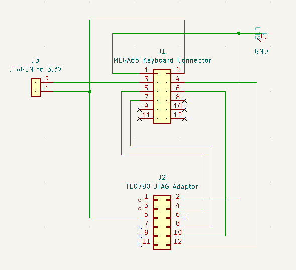
M65 KEYBOARD PIN 1 = GND = TE0790 PIN 2
M65 KEYBOARD PIN 2 = 3.3V = TE0790 PIN 5
M65 KEYBOARD PIN 3 = JTAGEN = can be left floating, else tie to 3.3V
M65 KEYBOARD PIN 4 = TMS = TE0790 PIN 12/H
M65 KEYBOARD PIN 5 = TCK = TE0790 PIN 4/C
M65 KEYBOARD PIN 6 = TDI = TE0790 PIN 10/F
M65 KEYBOARD PIN 7 = TDO = TE0790 PIN8/D
That all looks pretty straight-forward.
We then need dipswitch 4 on the TE0790 on, so that the TE0790 powers from USB, instead of from the connected device.
That seems to work, in so far as the JTAG adapter powers up, and the MEGA65 keyboard also powers up and shows the "ambulance lights" to indicate that it isn't communicating with a MEGA65 -- which is of course the case here, since there is no MEGA65 connected.
openFPGAloader can now see the FPGA:
$ openFPGALoader -d /dev/ttyUSB0 --detect
write to flash
Jtag frequency : requested 6.00MHz -> real 6.00MHz
index 0:
idcode 0x12ba043
manufacturer lattice
family MachXO2
model LCMXO2-1200HC
irlength 8
And it looks like I can push the bitstream to run live:
$ openFPGALoader -d /dev/ttyUSB0 --ignoreidcode impl1/megakey_impl1.bit
Jtag frequency : requested 6.00MHz -> real 6.00MHz
Open file: DONE
Parse file: DONE
Enable configuration: DONE
SRAM erase: DONE
Loading: [==================================================] 100.00%
Done
Disable configuration: DONE
But it can't write to the flash.
$ openFPGALoader -d /dev/ttyUSB0 -f --ignoreidcode impl1/megakey_impl1.bit
write to flash
Jtag frequency : requested 6.00MHz -> real 6.00MHz
Open file DONE
Parse file DONE
Enable configuration: DONE
SRAM erase: DONE
Detail:
Jedec ID : 00
memory type : 00
memory capacity : 00
Detail:
Jedec ID : 00
memory type : 00
memory capacity : 00
flash chip unknown: use basic protection detection
timeout: 0 0 1000
0
wait: Error
write en: Error
Erasing: [==================================================] 100.00%
Fail
Refresh: DONE
Error: Failed to program FPGA: std::exception
I had to modify openFPGAloader to even get to be able to flash, as the ID code between the bitstream and the board doesn't match, even though they are the same model of FPGA. I added the --ignoreidcode argument for that. If this ends up working, I'll send them a pull request, or at least fork the repo.
But first, we need to know why it can't flash.
Interestingly, openFPGAloader supports libgpiod, which we could leverage to distill a minimal bit-bashing JTAG implementation that could run natively on the MEGA65. But I'm not going to try to do that yet, and certainly not before we get openFPGAloader actually being able to program the flash in the lattice FPGA.
Ah, the solution is simple: use the .jed instead of the .bit file:
$ openFPGALoader -d /dev/ttyUSB0 -f impl1/megakey_impl1.jed
write to flash
Jtag frequency : requested 6.00MHz -> real 6.00MHz
Open file DONE
Parse file DONE
Enable configuration: DONE
SRAM erase: DONE
Enable configuration: DONE
Flash erase: DONE
Writing data: [==================================================] 100.00%
Done
Write program Done: DONE
Disable configuration: DONE
Refresh: DONE
So that all looks nice and simple.
The question is whether it is even worth designing a PCB, or whether folks who need to can be relied upon to just wire up the jumper leads between the MEGA65 keyboard cable and the TE0790. The latter is probably fine for doing a single keyboard, but if someone needs to flash lots of keyboards, e.g., during assembly, then the PCB would be really helpful. Like this:

The schematic is just what was described above: