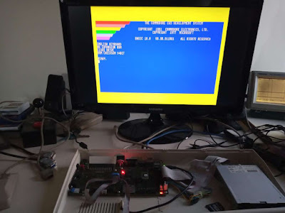
The datasheet explains that you have to set the WRTC (Write Real-Time Clock) bit, before the time can be set. The only problem is, is that this doesn't actually work. My best guess, is that the RTC registers have to be all set in a single write, for the write to take effect, whereas my SPI controller writes only one byte per transaction.
Although, it might not be required after all. This Linux driver for the RTC chip writes one byte at a time, and seems to indicate that writing to any of the RTC clock registers should start it running. However, nothing I have tried actually works to trigger this to occur.
Reading through the data sheet again, I was reminded that the RTC chip is very picky about writing to the clock registers: It requires that an I2C STOP signal occurs immediately after writing to the clock registers, so that partial writes will be ignored to help protect the integrity of the clock.
This led me through quite an adventure of tracking down and fixing a bunch of I2C management errors in mega65_i2c.vhdl, which collectively caused that problem, along with having the potential to cause some other I2C glitches. What it boiled down to, was that I was not allowing the I2C bus to go idle between the loop that reads all register values for displaying in the memory map, and when it writes a new value when requested by the CPU -- and vice versa.
With that fixed, I was finally seeing the STOP condition, which consists of the SDA line going high, while SCL stays high, as indicated by the vertical red-ish line in this simulation trace:
With that fixed and synthesised, I was then finally able to write to the RTC clock, and set it ticking (it doesn't start ticking until it has been initially set).
To make it easier for people to use, I have added getrtc() and setrtc() functions to the MEGA65 libc that I am writing. I have also added some initial documentation of the registers to the MEGA65 Book. I also updated the i2cstatus test program to show the current RTC (and other target specific information). It also allows editing of the RTC value:
Thanks to the libc functions that I wrote, the code to read and display the current time and date is quite simple:
void show_rtc(void)
{
getrtc(&tm);
printf("Real-time clock: %02d:%02d.%02d",
tm.tm_hour,tm.tm_min,tm.tm_sec);
printf("\n");
printf("Date: %02d-",tm.tm_mday+1);
switch(tm.tm_mon) {
case 1: printf("jan"); break;
case 2: printf("feb"); break;
case 3: printf("mar"); break;
case 4: printf("apr"); break;
case 5: printf("may"); break;
case 6: printf("jun"); break;
case 7: printf("jul"); break;
case 8: printf("aug"); break;
case 9: printf("sep"); break;
case 10: printf("oct"); break;
case 11: printf("nov"); break;
case 12: printf("dec"); break;
default: printf("invalid month"); break;
}
printf("-%04d\n",tm.tm_year+1900);
}
The main trick there, is that we will need to use a MEGA65 Enhanced DMA operation to fetch the RTC registers, because the RTC registers sit above the 1MB barrier, which is the limit of the C65's normal DMA operations. The easiest way to do this is to construct a little DMA list in memory somewhere, and make an assembly language routine that uses it. Something like this (using BASIC 10 in C65 mode):
10 RESTORE 110:FORI=0TO43:READA$:POKE1024+I,DEC(A$):NEXT:BANK 128:SYS1042
20 S=PEEK(1024):M=PEEK(1025):H=PEEK(1026)
30 D=PEEK(1027):MM=PEEK(1028):Y=PEEK(1029)+DEC("2000")
40 IF H AND 128 GOTO 80
50 PRINT "THE TIME IS ";RIGHT$(HEX$(H AND 63),1);":";RIGHT$(HEX$(M),2);".";RIGHT$(HEX$(S),2)
60 IF H AND 32 THEN PRINT "PM": ELSE PRINT "AM"
70 GOTO 90
80 PRINT "THE TIME IS ";RIGHT$(HEX$(H AND 63),1);":";RIGHT$(HEX$(M),2);".";RIGHT$(HEX$(S),2)
90 PRINT "THE DATE IS";RIGHT$(HEX$(D),2);".";RIGHT$(HEX$(MM),2);".";HEX$(Y)
100 END
100 DATA 0B,80,FF,81,00,00,00,08,00,10,71,0D,20,04,00,00,00,00
110 DATA A9,47,8D,2F,D0,A9,53,8D,2F,D0,A9,00,8D,02,D7,A9
120 DATA 04,8D,01,D7,A9,00,8D,05,D7,60
This program works by setting up a DMA list in memory at $0400 (unused normally on the C65), followed by a routine at $1012 ( = 1,042 in decimal) which ensures we have MEGA65 registers unhidden, and then sets the DMA controller registers appropriately to trigger the DMA job, and then returns. The rest of the BASIC code PEEKs out the RTC registers that the DMA job copied to $0400 -- $0407, and interprets them appropriately to print the time.
The curious can use the MONITOR command, and then D1012 to see the routine.
If you want a running clock, you could replace line 100 with GOTO 10. Doing that, you will get a result something like the following:
If you first POKE0,65 to set the CPU to full speed, the whole program can run many times per second. There is an occasional glitch, if the RTC registers are read while being updated by the machine, so we really should de-bounce the values by reading the time a couple of times in succession, and if the values aren't the same both times, then repeat the process until they are. This is left as an exercise for the reader.
Finally, I updated the auto-documentation in the VHDL source, so that the new registers will be automatically documented in the MEGA65 Book, which is already getting close to 500 pages. I'm expecting that the MEGA65 Book will be close to 1,000 pages when complete -- not that this should be scary, but rather reflect the depth of documentation that we want to provide potential users and developers of the machine.


