In the last post, I managed to get a fair bit of progress on the ability to format disks in the MEGA65's internal drive. I am now able to write data and synchronisation bytes, and generally make a valid track of data... except for the CRC fields in the sector header and sector data regions. So now I need to look for some nice simple code to implement this.
We already have a working VHDL implementation that works on a bit-by-bit basis. But for software formatting in my test programme, we ideally need a nice simple byte-oriented algorithm. The C65 ROM must clearly have one, so lets see how it is done in there.
The first part of this is to look at the track formatting code. The wttrk routine does the actual writing of tracks, writing out the ten sectors, including the header and initial CRCs. The relevant part looks like this:
ldy #4 ;Write 4 header bytes
ldx #$ff
30$ lda header-1,y
40$ bit stata
bpl wtabort ; oops
bvc 40$
sta data1
stx clock
dey
bne 30$
lda sec ;Convert sector number into a
asl a ; CRC pointer
tay
lda crc,y
ldx #$ff
50$ bit stata ;Write 2 byte header CRC
bpl wtabort ; oops
bvc 50$
sta data1
stx clock
lda crc-1,y
60$ bit stata
bpl wtabort ; oops
bvc 60$
sta data1
stx clock
ldy #42 ;Write post ID gap
70$ lda gap1-1,y
ldx gap1clk-1,y
80$
We can see from this that it pulls the CRC bytes from an array called crc. This makes sense, because there are only a few hundred CPU cycles at 3.5MHz between each byte that must be written, which is in sufficient time to calculate the CRCs on the run. So lets now try to find where the crc array gets initialised, where we find the following gem:
;*----------------------------------------------------------------------*
;* Calculate the 2 byte CRC for each sector header of an entire track *
;* of 10 sectors. AXYZ are trashed. *
;* *
;* This routine is based on the Cyclical Redundancy Check on the *
;* polynomial: A^16+A^12+A^5+1. *
;* *
;* HEADER contains TRACK,SIDE,SECTOR,2 [sector size] *
;* *
;* DO WHILE ne = 0 *
;* DO FOR each bit in the data byte (.a) [from lsb to msb] *
;* IF (LSB of crc) EOR (LSB of data) *
;* THEN CRC = (CRC/2) EOR polynomial *
;* ELSE CRC = (CRC/2) *
;* ENDIF *
;* LOOP *
;* LOOP *
;*----------------------------------------------------------------------*
So not only have we found the routine, but a really nice piece of pseudo-code that explains how they have calculated it.
Oddly, however, this algorithm seems to indicate that we should start with the LSB, and divide the CRC, while the VHDL code we have seems to work the other way around, starting with the MSB, and shifting the CRC in the other direction. The structure ends up with the same result -- just the bit order is reversed:
The relevant part of the VHDL is:
value(15 downto 1) <= value(14 downto 0);
value(12) <= value(11) xor (byte(7) xor value(15));
value(5) <= value(4) xor (byte(7) xor value(15));
value(0) <= (byte(7) xor value(15));
byte(7 downto 1) <= byte(6 downto 0);
bits_left <= bits_left - 1;
This works because the XOR (==EOR) with value(15), which means bit 15 of the reversed CRC, acts to toggle the effect of EORing with bit 7 of the reversed incoming byte. That is, it has the effect of saying:
IF value(15)='1' then
value(12) <= NOT (value(11) XOR byte(7))
ELSE
value(12) <= value(11) XOR byte(7)
END IF;
Now, as I have written that, I have got myself worried, because it doesn't conditionally apply the bit from the incoming byte, but rather simply inverts the computed combination of the bit from the byte and from the CRC. So I think I would like to see an independent implementation, to help clear up this confusion.
Here is the simplified version of an implementation I found here that calculates the CRC correctly:
unsigned short crc_ccitt[256];
// crc16 init table
void crc16_init()
{
for (i = 0; i < 256; i++)
{
uint16_t w = i << 8;
for (a = 0; a < 8; a++)
w = (w << 1) ^ ((w & 0x8000) ? 0x1021 : 0);
crc_ccitt[i] = w;
}
}
// calc crc16 for 1 byte
unsigned short crc16(unsigned short crc, unsigned short b)
{
crc = (crc << 8) ^ crc_ccitt[((crc >> 8) & 0xff) ^ b];
return crc;
}
What I like about this version is that it really is super simple. And it works :) To use it, you just call it with the old CRC value and the byte to include. The initial CRC value should be $FFFF. When we do that, we then get $B230 as the CRC for the initial $A1,$A1,$A1,$FE part of the sector header, which is the hard-coded initial value the C65 DOS ROM uses as well. We can calculate that here with something like this:
// Calculate initial CRC of sync bytes and $FE header marker
crc=crc16(0xFFFF,0xa1);
crc=crc16(crc,0xa1);
crc=crc16(crc,0xa1);
crc=crc16(crc,0xfe);
So that's all good.
Now what I am still not sure, is whether our VHDL implementation is really working properly. It seems that we do really use the CRC there to check things, so presumably it does, and I'm just too tired to be able to work through it to convince myself that it really does work. Simpler is to just make a test harness that feeds the same four bytes into the VHDL, and see if we get the correct value out the other end, which it does:
src/vhdl/crc1581.vhdl:58:9:@111ns:(report note): CRC reset
src/vhdl/crc1581.vhdl:58:9:@135ns:(report note): CRC reset
src/vhdl/crc1581.vhdl:58:9:@159ns:(report note): CRC reset
src/vhdl/crc1581.vhdl:58:9:@183ns:(report note): CRC reset
src/vhdl/mfm_bits_to_gaps.vhdl:73:11:@999ns:(report note): MFMFLOPPY: Decrement bits_queued to 15
src/vhdl/crc1581.vhdl:54:9:@1215ns:(report note): CRC fed with $A1
src/vhdl/mfm_test.vhdl:381:5:@2220ns:(report note): CRC = $443B
src/vhdl/mfm_bits_to_gaps.vhdl:73:11:@2943ns:(report note): MFMFLOPPY: Decrement bits_queued to 14
src/vhdl/crc1581.vhdl:54:9:@3231ns:(report note): CRC fed with $A1
src/vhdl/mfm_test.vhdl:388:5:@4240ns:(report note): CRC = $968B
src/vhdl/mfm_bits_to_gaps.vhdl:73:11:@4887ns:(report note): MFMFLOPPY: Decrement bits_queued to 13
src/vhdl/crc1581.vhdl:54:9:@5247ns:(report note): CRC fed with $A1
src/vhdl/mfm_test.vhdl:395:5:@6260ns:(report note): CRC = $CDB4
src/vhdl/mfm_bits_to_gaps.vhdl:73:11:@6831ns:(report note): MFMFLOPPY: Decrement bits_queued to 12
src/vhdl/crc1581.vhdl:54:9:@7263ns:(report note): CRC fed with $FE
src/vhdl/mfm_test.vhdl:402:5:@8280ns:(report note): CRC = $B230
We nicely see the $B230 value at the end, so all is well.
So now lets use our CRC routine in the C code to prepare the CRC values, and then update the track formatter to write the computed CRC bytes out, and see if we then have apparently valid tracks.
With a bit of fiddling around, I have managed to pre-calculate the sector header data values, so that after formatting a track, the disk read logic correctly detects the sectors as they pass under the head -- so this is great progress.
I have also made an attempt to write the correct sector data CRC bytes as well, but haven't had time to test that. I'm pretty exhausted tonight, so that will have to wait for tomorrow at least now. What I will probably do, is patch my disk track format test routine to instead format the entire disk. I can then use the existing test for reading all disk sectors to verify if it has worked. I might also patch the read test code to use the "match any sector" mode of the floppy controller, so that we don't waste time due to interleave, nor waste too much time on bad tracks, as we can just allow a set number of rotations per track, before moving on to the next track, unless we have read all sectors correctly early, in which case, proceed. But that's all window dressings really... the main game is to first see if we are able to correctly format a disk...
Tomorrow is here, and I have modified the floppytest.c programme to format the entire disk, instead of just one specific track. This includes formatting both sides of each track... and after a rather minor amount of fiddling, it works.
I did initially have too long a delay after stepping the disk, which meant that the index hole was in the wrong place, but that was easy to fix. Out of curiosity, I also wondered how many tracks I can really format on these Alps drives. It seems like 84 and maybe 85 tracks is possible, at least on my unit here.
The only intermittent problem I am seeing, is that the VFDC floppy virtualisation stuff is sometimes being triggered. That is, the machine thinks that a given floppy access should be virtualised, rather than to a real drive. I am seeing the bit set for the 2nd drive to be virtualised is set, which it probably shouldn't be. But even if it is, then it still shouldn't be getting triggered.
Looking at where the CPU is waiting, its a virtualised floppy read that it thinks is going on. This is doubly weird, because we are in the middle of a track format, not triggering a sector read, so there is a 2nd reason why it shouldn't be able to be triggered. I wasn't running the absolute latest bitstream, so I will try it with that bitstream a few times, and see if it still occurs.
Meanwhile, lets go back to that problem with the order of writing the data and clock bytes: The C65 ROM sets the clock byte after the data byte, which causes us problems. The C65 ROM prepares A and X with the data and clock values, and then writes them in immediate succession. This suggests to me that they were working around some bug in the F011 controller that was quite time sensitive, as otherwise they could have just used a LDA #datavalue / STA wdata / LDA #clockvalue / STA wclock sequence.
But for us, its a real pain, because the logical way to handle things is to latch the clock value when the data value is written to. Our current MFM encoder requests the next byte to be written as soon as it runs out of bits from the last byte. As the raw flux data rate for 720KB disks is 500kbit/sec, this means that there are only two cycles at 1MHz, or about 7 cycles at 3.5MHz from when the request is raised, to when the first bit is required.
Given that we have a busy wait loop watching for the signal to be raised, this basically means that there is no time slack for waiting for the clock value to get written later. In fact, it suggests that the current format test programme I have written would probably not work at 3.5MHz with our implementation. And things would only get worse for HD or ED disks, where the data rate is 2x and 4x that of 720KB DD disks.
To solve this, I think I am going to have to make the MFM encoder buffer one extra byte and clock value, so that we have a whole byte in reserve at all times, thus increasing the slack to ~7x8 = 56 cycles at 3.5MHz. This can then be setup to latch the clock value five 3.5MHz clock cycles after the data value has been written, so that we remain bug-compatible with the real C65 F011 floppy controller.
So to summarise, we need to raise the request for another data byte whenever we don't currently have a spare byte buffered, and then latch the clock value at the time we transfer that byte from the buffer to the active output stage. This is a very simple way to implement this. Indeed, this structure might very well be exactly what the C65's F011 did, and how the bug got created in the first place. So that's how I will implement it.
While that is synthesising, I might take a look at this erroneous triggering of the VFDC hypervisor interrupt during formatting. It only happens once every few times I go to format a disk, which itself takes about a minute, so its a little bit annoying in that it doesn't just happen on demand. This also makes it hard to know for sure that it is fixed. So I will modify the floppytest.c programme to try formatting in an infinite loop.
Meanwhile, the synthesis run has finished, so I can look at whether the changes have worked. The existing version of floppytest.c now doesn't write valid tracks anymore. But that could be because I was writing clock values before data values. So first step is to make it assume bug-compatibility with the F011 by writing the data byte, and then the clock byte, and see if that fixes it. If not, its time to do more raw captures, and see what is going on.
Capturing the the raw track data has immediately revealed the problem: The 3rd SYNC byte is being sent as a normal $A1 with clock $FF, instead of clock $FB, e.g.:
(15 bytes since last sync)
Sync $A1
Sync $A1
$a1 $fe $00 $00 $00 $02 $ce $6e $4e $4e $4e $4e $4e $4e $4e $4e
$4e $4e $4e $4e $4e $4e $4e $4e $4e $4e $4e $4e $4e $4e $4e $00 $00
$00 $00 $00 $00 $00 $00 $00 $00 $00 $03 $11
So something is amiss with the buffering and latching of the clock.
A bit of fiddling around, and I think I have it right now. Synthesis will run over night, and I'll see if I get a bit of time tomorrow to test it out.
It's tomorrow (again), and its still doing the same thing. So I need to try to reproduce the problem under more detailed simulation. The previous simulation I did was just writing data and clock bytes simultaneously, rather than one after the other in separate CPU instructions.
Its now a couple of days later, as I was tied up for a while with family taxi duties and an advanced driving course I had been wanting to do for a while (heavy truck driving, with non-synchromesh "road ranger" style gearbox, for the interested). I am starting back by trying to simulate the floppy track formatting with real CPU instructions injecting the data.
Simulating this didn't show up the problem... Ah, not quite... I have caught it in the act :) So let's try to understand what is going on here...
These lines are a bit long, which is a bit of a pain. But we can see some things, including some fishy things, happening along the way, so lets go through the simulation log:
@3135ns: $A51D 8D 87 D0 sta $D087 A:A1 X:00 Y:00 Z:3F
@3399ns: $A522 8D 88 D0 sta $D088 A:FB X:00 Y:00 Z:3F
mfm_bits_to_gaps.vhdl:140:11:@3423ns: latching clock byte $FB
@3663ns: $A527 8D 81 D0 sta $D081 A:A1 X:00 Y:00 Z:3F
sdcardio.vhdl:1831:19:@3663ns: FLOPPY: Asked for track format
sdcardio.vhdl:1836:21:@3663ns: FLOPPY: Real drive selected, so starting track format
The floppy controller then waits for the index hole to come by, before actually starting to format the disk:
cpu_test.vhdl:@11us: FLOPPY: START of index hole
sdcardio.vhdl:@11007ns: FLOPPY: Format Track Sync wait: f_index='0', last_f_index='1'
Once the index hole arrives, the floppy controller begins to write the pre-written byte (data $A1, clock $FB), and does this correctly.
sdcardio.vhdl:@11007ns: FLOP: (format track wait) Writing byte $A1 to MFM write engine.
sdcardio.vhdl:@11055ns: FLOPPY: Format Track Active: fw_ready_for_next = '0', last_fw_ready_for_next='1'
mfm_bits_to_gaps.vhdl:@11055ns: MFMFLOPPY: emitting buffered byte $A1 (latched clock byte $FB) for encoding.
Once it commits to writing that byte, it immediately lets the CPU know that it can provide the next byte, which it will buffer for ready when the currently being written byte is finished being written:
sdcardio.vhdl:@11079ns: FLOPPY: Format Track Active: fw_ready_for_next = '1', last_fw_ready_for_next='0'
sdcardio.vhdl:@11079ns: FLOPPY: Format requesting next byte
sdcardio.vhdl:@11079ns: FLOP: (format track) Writing byte $A1 to MFM write engine.
sdcardio.vhdl:@11127ns: FLOPPY: Format Track Active: fw_ready_for_next = '0', last_fw_ready_for_next='1'
This tells the CPU it should supply the next byte, which it does, the 2nd sync mark $A1 with clock byte $FB:
@11823ns: $A52F 8D 87 D0 sta $D087 A:A1 X:00
@12087ns: $A534 8D 88 D0 sta $D088 A:FB X:00
Meanwhile, the floppy controller is actually writing the first sync mark out, and when done, tells the CPU its ready for the next byte to be written:
mfm_bits_to_gaps.vhdl:@42375ns: MFMFLOPPY: emitting buffered byte $A1 (latched clock byte $FB) for encoding.
sdcardio.vhdl:@42399ns: FLOPPY: Format Track Active: fw_ready_for_next = '1', last_fw_ready_for_next='0'
sdcardio.vhdl:@42399ns: FLOPPY: Format requesting next byte
sdcardio.vhdl:@42399ns: FLOP: (format track) Writing byte $A1 to MFM write engine.
sdcardio.vhdl:@42447ns: FLOPPY: Format Track Active: fw_ready_for_next = '0', last_fw_ready_for_next='1'
So the CPU provides the 3rd $A1/$FB sync mark, while the floppy controller writes out the 2nd one:
@43431ns: $A53C 8D 87 D0 sta $D087 A:A1 X:00 Y:00 Z:3F
@43695ns: $A541 8D 88 D0 sta $D088 A:FB X:00 Y:00 Z:3F
mfm_bits_to_gaps.vhdl:@73863ns: MFMFLOPPY: emitting buffered byte $A1 (latched clock byte $FB) for encoding.
When the floppy controller is done writing the 2nd one, it tells the CPU its ready for the next byte, which will be the $FE/$FF byte, while it writes out the 3rd $A1/$FB that it has buffered:
sdcardio.vhdl:@73887ns: FLOPPY: Format Track Active: fw_ready_for_next = '1', last_fw_ready_for_next='0'
sdcardio.vhdl:@73887ns: FLOPPY: Format requesting next byte
sdcardio.vhdl:@73887ns: FLOP: (format track) Writing byte $A1 to MFM write engine.
sdcardio.vhdl:@73935ns: FLOPPY: Format Track Active: fw_ready_for_next = '0', last_fw_ready_for_next='1'
So the CPU obediently provides the $FE/$FF byte as the next byte to be written to the floppy:
@75039ns: $A549 8D 87 D0 sta $D087 A:FE X:00 Y:00 Z:3F
@75303ns: $A54E 8D 88 D0 sta $D088 A:FF X:00 Y:00 Z:3F
Which then causes the floppy to latch the new clock value of $FF, the problem being, that this then gets used for the 3rd $A1 mark byte, instead of the correct clock byte $FB that should have been used.
mfm_bits_to_gaps.vhdl:@75327ns: latching clock byte $FF
mfm_bits_to_gaps.vhdl:@105351ns: MFMFLOPPY: emitting buffered byte $A1 (latched clock byte $FF) for encoding.
So that is where the problem is occurring. Now I just have to work out why. In the process I also realised that the C65 DOS actually asks for a gap byte to be written before issuing the format command, and then sends the three gap bytes. If I do that, then I end up writing four $A1 bytes, three with $FB clock byte, and then one with $FF clock byte. Thus there are two problems to solve.
If I had a real C65 here, it would be interesting to know if it writes the gap byte, and then 3 sync bytes, or just 3 sync bytes in this case. But I don't, and it would require a bit of fiddly monitoring with oscilloscope etc. So I need to figure out a solution in any case.
Looking closer, it might actually be that the data byte is not being latched at the right time, and that problem is that the data byte is delayed by one byte when being written, when compared with the clock.
Indeed it looks to be the case: I was only latching the data byte when the previous byte finished sending, which could be some time after the clock byte gets latched. So I am making it latch new data bytes whenever they are presented. So I have fixed that, so data bytes just get latched whenever they are presented, and also realised that the C65 DOS does in fact wait for the MFM writer to request the next byte before sending the first sync mark after issuing the format track command. Once I had those two things in place, it now looks very promising:
src/vhdl/mfm_bits_to_gaps.vhdl:139:9:@3183ns:(report note): MFMFLOPPY: emitting buffered byte $4E (latched clock byte $FF) for encoding.
src/vhdl/mfm_bits_to_gaps.vhdl:139:9:@34503ns:(report note): MFMFLOPPY: emitting buffered byte $A1 (latched clock byte $FB) for encoding.
src/vhdl/mfm_bits_to_gaps.vhdl:139:9:@65991ns:(report note): MFMFLOPPY: emitting buffered byte $A1 (latched clock byte $FB) for encoding.
src/vhdl/mfm_bits_to_gaps.vhdl:139:9:@97479ns:(report note): MFMFLOPPY: emitting buffered byte $A1 (latched clock byte $FB) for encoding.
src/vhdl/mfm_bits_to_gaps.vhdl:139:9:@128967ns:(report note): MFMFLOPPY: emitting buffered byte $FE (latched clock byte $FF) for encoding.
Now it is time to synthesise again, and see if it works on hardware :)
... and it does! The disk read test functions correctly after. To make really sure it works, I even wrote a utility that just writes constant flux to the disk, to erase all vestigates of sectors, and after that, I run my format test, and it results in a disk with readable sectors.
So now it might be time to try the BASIC 10 HEADER command, and see if I can make it format a disk. When it gets to the point where it wants to populate the directory track it will of course fail at the moment, because I still have yet to implement writing to sectors. But it _should_ write the sector structure to disk. And because I can flux erase the disk first, I can be really sure that the BASIC 10 header command has done the formatting. First attempt was not very successful. After the drive chugged strangely for a while, I saw this:

The 27 read error means that the FDC was not able to find a valid sector header.
One problem I am expecting at the moment, is that with the auto-tune function enabled, the drive may well be hunting tracks for no good reason. And during a format, it should be disabled anyway.
Disabling it during the format doesn't help any.
In that case, the problem would seem to be that the format code in the C65 ROM doesn't wait for the track to be formatted, as it is churning through the tracks way too fast: Found the problem causing that, which is that I wasn't setting the BUSY flag of the floppy controller when writing a track. As a result, the C65 DOS (not unreasonably) thinks that it the write has aborted before it even gets to write anything. So time to resynthesise again with a fix for that...
Well, now it starts to format, and goes through several tracks before hanging waiting for the BUSY flag on the floppy controller to go clear. But something curious must be happening, because the track format command has no code path where the BUSY flag doesn't get cleared when it ends, and it ends once it reaches the next index hole pulse. Also, there is something curious going on, because even for the tracks that it has formatted, some sides don't seem to have been formatted, as you can see in this report of which sectors can be read after the HEADER command ran and hung (I stopped it after a while, as it reached the part of the disk beyond where it hang):

As mentioned, we see that some sides of some tracks have not been formatted properly. There is also that single sector on track 19 that read, but whether that was the track not having been properly erased before or something, I'm not sure. It's a mystery I will have to try to solve later.
First, though, I want to do a raw track read on one of those tracks that fail, and see what I can see there. In particular, I want to know if something is written, perhaps the wrong something, or whether the tracks are just plain empty.
Most curious... There appears to be quite valid sectors written on track 0, side 1, for example. For example, we have:
$b2 $00 $00 $00 $00 $00 $00 $00 $00 $00 $00 $00 $14
(13 bytes since last sync)
Sync $A1
Sync $A1
Sync $A1
$fe $00 $01 $01 $02 $fd $5f $4e $4e $4e $4e $4e $4e $4e $4e $4e
$4e $4e $4e $4e $4e $4e $4e $4e $4e $4e $4e $4e $4e $4e $4e $4e $4e
$00 $00 $00 $00 $00 $00 $00 $00 $00 $00 $00 $00
(45 bytes since last sync)
Sync $A1
Sync $A1
Sync $A1
$fb $00 $00 $00 $00 $00 $00 $00 $00 $00 $00 $00 $00 $00 $00 $00
$00 $00 $00 $00 $00 $00 $00 $00 $00 $00 $00 $00 $00 $00 $00 $00 $00
$00 $00 $00 $00 $00 $00 $00 $00 $00 $00 $00 $00 $00 $00 $00 $00 $00
$00 $00 $00 $00 $00 $00 $00 $00 $00 $00 $00 $00 $00 $00 $00 $00 $00
...
So we have the three sync $A1 marks, then $FE for sector header, then track $00, sector $01, side $01, sector size = $02 (512 bytes), CRC = $FD5F. That should be valid. I might try formatting it with my test utility again, and see whether I have a different CRC for that sector, perhaps.
Hmm... Looks like I have been writing $00 into the side, but calculating the side 1 sector header CRCs using $01. How on earth that was ever reading, I don't know. So first step is to fix my floppy test programme, and then try that again, to see if side 1 of a disk it formats reads properly...
We also have the hanging, presumably due to the virtualised disk access triggering again sometimes, which may well be why the track formatting under the C65 ROM hangs. But we will get to that later. First, let's keep looking at the side 1 sectors...
First up, realised I was swapping sides 0 and 1, so fixed that. Now it looks essentially identical:
Sync $A1
Sync $A1
Sync $A1
$fe $00 $01 $01 $02 $fd $5f $4e $4e $4e $4e $4e $4e $4e $4e $4e
$4e $4e $4e $4e $4e $4e $4e $4e $4e $4e $4e $4e $4e $4e $00 $00 $00
$00 $00 $00 $00 $00 $00 $00 $00 $00
(42 bytes since last sync)
Sync $A1
Sync $A1
Sync $A1
$fb $00 $00 $00 $00 $00 $00 $00 $00 $00 $00 $00 $00 $00 $00 $00
$00 $00 $00 $00 $00 $00 $00 $00 $00 $00 $00 $00 $00 $00 $00 $00 $00
$00 $00 $00 $00 $00 $00 $00 $00 $00 $00 $00 $00 $00 $00 $00 $00 $00
So what is going on? Time to try formatting the disk again using HEADER after doing a flux wipe, and see if the pattern of missed tracks is constant. Could it perhaps just be the virtual FDC stuff tripping it up again? It's possible, as I don't seem to be able to get through a whole disk of any action without it locking up. Alternatively, it could be that the index hole line needs to be de-bounced. I'll add some de-bounce logic to it, to see if that helps. That will need to re-synthesise.
In the meantime, let's try to format a disk using the C65 DOS again, after I get the flux wipe routine enough of the disk. It got to track 30 this time, which should be far enough for our current purposes. The pattern is a bit different this time, with some random bad sectors, as well as complete missed sides:

In case it was the position of the index hole as the disk rotates that is causing the problem, I tried modifying the disk wipe routine to use one of the debug registers to check for an edge on the index hole signal before issuing the track format command. But that doesn't seem to have made any difference, no matter if I look for a positive or negative edge: It still hangs after some random number of tracks, often less than 20. This didn't seem to be an issue with the previous bitstream. The current bitstream makes timing closure, so it shouldn't be a bad synthesis run to blame.
But the only changes between the two builds was the setting of the BUSY flag during track format operations -- which we don't even check in any meaningful way. It is examined, but the loop just aborts the writing of the current byte if it goes non-busy, which it should within one rotation.
Well, I found a bug in the checking of the BUSY flag in my disk wipe code, but after having fixed that, I can see that indeed the floppy controller can get stuck in a state where it flags perpetually busy, without saying it needs another byte. So that's a different type of failure mode.
For the first type, I added some debugging which reveals that when it does stop early, it is always before even a single byte has been written to the floppy. That makes me think that the debouncing should fix that problem.
As for the second mode, this shouldn't be possible if the index sensor keeps working, as we stop the track format operation as soon as the index sensor line goes low. But again, perhaps it is some glitching on the INDEX line causing it. Anyway, I am synthesising a bitstream now with de-bouncing of the INDEX line, effectively requiring it to go low for 8 cycles at 40.5MHz = ~200ns, instead of only ~25ns. This should fix any problems with the INDEX line bouncing low briefly when it is released (which I suspect is the most likely time for glitching).
Anyway, I am writing the above while I test this bitstream, and it does seem to be proceeding through with formatting the complete disk. It still complains about a 27 READ ERROR for track 40, sector 0 at the end, but that's not unexpected, given that actually writing sectors still doesn't work. But its still nice to see it chug through writing to all the tracks. Now for the moment of truth to see how many of those tracks we think we have actually written too...
And it is looking a lot better. There are no more track sides missing. But we are still seeing some random bad sectors, as can be seen here:

I have a theory that those could possibly be caused if the C65 ROM is not quite feeding bytes in fast enough. My reason for suspecting this, is that when I looked at the earlier track capture from the C65 ROM formatting a disk, was that there was a couple of corrupted bytes, that looked like a bit had been missed or was slightly late. The way to test that hypothesis is to switch the machine to 40MHz while formatting and see if it fixes it.
Indeed my theory is right: at 40MHz, the disk is perfectly formatted, with no bad sectors:

Deft also wanted to be sure it would format from C64 mode, so I did the same test from there (without forcing 40MHz), and it also completes with the same sector write error (as expected):

Again, ignore the stray "B" which is a glitch in my screen capture method.
Formatting from C64 mode also resulted in some stray bad sectors. It also did some nasty auto-tune track hunting, so I am adding an inhibitor for that for 0.5 seconds after any write command is issued. In reality, the auto-tuner should only be needed very rarely, when the drive mis-steps (which I am wondering if it isn't caused by us having the STEP line pulses too narrow).
Meanwhile, it occurred to me that the errors writing to the disk during formatting are quite likely due to badline emulation not turning off when the VIC-IV screen is blanked -- and it looks almost certain that this is the case. So if I fix that, then formatting at 3.5MHz C65 mode or 1MHz C64 mode should then work without errors.
... Well, except that apparently the logic in the VIC-IV should already be preventing badlines when the blank bit of D011 is set. But I can test that, by disabling badline emulation, and seeing if it makes formatting work correctly, so let's give that a quick try...
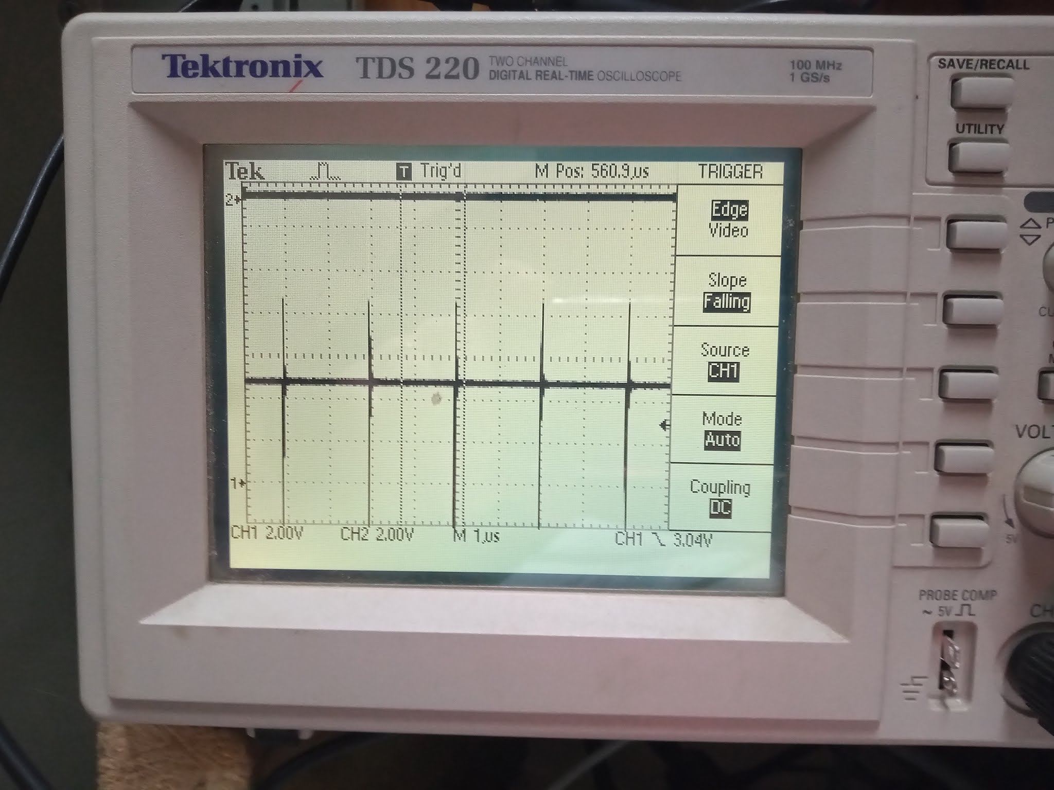
While that is running, I also watched the STEP line on the oscilloscope, and it looks like we have a bug with our handling of that, which is probably what necessitated the whole auto-tune stuff to begin with: The pulse width varies, because the STEP line is cancelled using a 16KHz timer, but the timer runs asynchronously, so it is possible the STEP line gets asserted just before the timer runs out, resulting in a pulse as narrow as 25ns, which is probably then going to be ignored by the drive, if it even makes its way through the voltage level converter. So I'll fix that in the synthesis run, too.
Now, back to the badline emulation, disabling it didn't fix that problem. So it must presumably be something else. Maybe I have the cycle counts for one of the instructions wrong, which causes it to take just a fraction too long, making it marginal. Or maybe my data rate for the floppy drive is just marginally too fast. I'll have a think about it tomorrow, now, as its got late again.
Meanwhile, while I think about that, I have synthesised the STEP pulse width fix, so will test that. And I have also started to synthesise a potential to fix to the "red vertical line" bug when exiting the freezer, while I am fiddling with things. But let's take a look at those STEP line pulses, and see if they are now all constant width. Which they are now, which is good. So hopefully that fixes the floppy seeking errors.
Now, in the meantime, I have run a format with the latest bitstream, just because I can. It is still getting a few errored sectors. So now I am trying to slow the drive data rate down a bit, to see if I can find the point at which the errors disappear, so that I can get an estimate of the CPU speed difference required. Not sure if it will really give me the info I need, but as my son wants me playing minecraft for a while, I can set these running in between mining sorties.
$D6A2 = $51 = 81 = normal = some errors
$55 = 85 = a bit slower = 2 errors
$5A = 90 = 10% slower = 3 errors
$60 = 96 = ~15% slower = not enough time to write the whole track
... but at that point, there are no errors. So its possible 15% is enough perhaps for the CPU speed issue, but it must be CPU timing, rather than floppy data rate, since we still have errors even after slowing the data rate to the point where we can no longer fit a whole track. So its probably time to check the cycle counts for the instructions that get run in the loop, to see if I accidentally charge one cycle too many for any of them.
But anyway, that new bitstream has been built that should fix the freeze menu cross-hair but. I should also do a bit more testing of the STEP fix, to make sure that it really has solved the mis-stepping bug that the auto-tune thing was originally added to solve. Then I think I will probably focus on getting sector writing working, and just have the errata for now, that you have to have the CPU set to 40MHz when formatting a disk, until I find the root cause of the CPU slowness issue.
Ok, bitstream has synthesised. I can confirm that the cross-hairs bug is now fixed, in that the cross-hair position is correctly restored following a freeze. The Freeze Menu does need to clear the cross-hair position, though, when entering the Freeze Menu, though, so that it doesn't stay visible. So that's one of two problems confirmed fixed.
Now for the STEP bug. We have a random seeking test in the histogram/seek tests mode of floppytest.c. This is activated just by pressing 1 to select the histogram tests, then m, to select manual seeking (i.e., disable auto-tune), and then pressing s to start random seeking, which it will then do continuously until stopped. If it fails a seek, it will complain by stopping and waiting for the seek to complete -- which it never will if the seek is incomplete. This looks something like this when running:

And the target track number will just keep increasing as it runs. It's already done several hundred seeks, for example:

The spikes on the line at the bottom shows a histogram of flux reversal intervals, i.e., the higher a peak, the more flux reversals after the period of time indicated by the position of the spike from left to right. The further right, the longer the intervals. As this disk has been formatted fresh and empty, there is mostly just a really big spike that corresponds to the repeated recording of 0s.
I'll let that keep going for a while, until it has done several thousand seeks at least, without any errors. If it survives that, then I'll assume that it is working properly. My recollection is that it used to fail after less than a couple of hundred random track seeks previously, by way of comparison.
So now, while we listen to the random floppotron music of a drive seeking around the place, its time to finally tackle writing sectors once a disk has been formatted. This is because a disk which has been formatted, but has no data on it, is really rather useless, as we can see here when I ran a DIR command on a disk after formatting it in the MEGA65 just now:

Writing sectors is quite different to formatting a track, because we first need to read the disk until we find the header for the correct sector, and then we have to carefully time when to start writing the actual sector data following that, so that it doesn't run too long and write over the header for the next sector. Also, because its impossible to get the timing 100% accurate, we have to have a way of synchronising when reading back. This is why there are 3 SYNC mark bytes ($A1 data, $FB clock, as for the sector headers), so that this can be picked up unambiguously.
We also need to write a few gap bytes before writing the SYNC marks, just in case the head on the floppy takes a while to start writing. There is also the issue that on some drives the write head and read head are separate, and can have either or the other "ahead" on the disk. This means that we need to wait just a little while after reading the sector header before we start writing, in case the write head is behind the read head, and that can potentially overwrite the bytes we just read from the sector header, which would leave the sector header destroyed, and thus the sector irretrievable.
Reading through this, it seems that we can immediately switch the head to write mode after we find the sector header. It does still take a few bits of write time before the erase head activates, due to its position "up track", and writing actually takes effect. But this is not a problem for us: As soon as we have the valid header and CRC bytes, we are free to start writing gap bytes, then the sync marks, $FB data marker, sector bytes and sector CRC bytes. So that's what I will try.
Meanwhile, the random track seeking has continued without incident, now having done more than 15,000 random track seeks, which means in reality about 40x that number of individual track steps, i.e., around 600,000 seeks, without any problems, so I think we can safely say we have fixed that bug:

So now its back to sector writing.
Basically my approach is to wait for the sector header to come by, and then to write the various fields, including the data and checksum bytes. The main part of the code is pretty simple. Let's start with the part where we wait for the sector header to come by:
when F011WriteSectorRealDriveWait =>
-- Wait until the target sector header is found, or
-- six index pulses have passed
-- Wait until we get a fresh event of hitting the sector we
-- are looking for.
if fdc_sector_found='1' and last_fdc_sector_found='0' then
-- Indicate that we still have the gap and sync mark bytes etc to write
fdc_write_byte_number <= 0;
-- And immediately open the write gate
f_wgate <= '0';
-- Ask for sector buffer to get ready to feed us bytes, beginning
-- at the start of the sector buffer
f011_buffer_disk_address <= (others => '0');
f011_buffer_disk_pointer_advance <= '0';
sb_cpu_read_request <= '0';
sb_cpu_reading <= '0';
-- And now start feeding bytes
sd_state <= F011WriteSectorRealDrive;
end if;
if fdc_rotation_timeout_reserve_counter /= 0 then
fdc_rotation_timeout_reserve_counter <= fdc_rotation_timeout_reserve_counter - 1;
else
-- Out of time: fail job
report "Cancelling real sector write due to timeout";
f011_rnf <= '1';
fdc_read_request <= '0';
fdc_bytes_read(4) <= '1';
f011_busy <= '0';
sd_state <= Idle;
end if;
What that basically does is wait until we see the sector we want to write come by (i.e., the found sector flag goes from low to high), and when this occurs, switch the head from read to write mode, and move to the F011WriteSectorRealDrive state that does the actual sector writing. The rest of it just enforces a sensible timeout, so that if the sector is not present, it doesn't hang forever.
Now, looking at the F011WriteSectorRealDrive state, we basically have a big case/switch statement that decides what we should be writing, and updates the pointer in the sector buffer as it goes along, and updates the CRC calculation as well for the data bytes, so that the CRC can be written out correctly at the end.
when F011WriteSectorRealDrive =>
-- Write the various bytes of the sector, including the sync marks etc
-- Note that it is not possible to read from the sector buffer while
-- doing a write, as the FDC requires the memory bandwidth of the
-- sector buffer.
-- (We could work around this by buffering the bytes from the buffer
-- as we go, but let's keep things simple for now.)
sb_cpu_read_request <= '0';
crc_feed <= '0';
if fw_ready_for_next='1' then
fdc_write_byte_number <= fdc_write_byte_number + 1;
case fdc_write_byte_number is
when 0 to 22 =>
-- Write gap $4E bytes
f011_reg_clock <= x"FF";
fw_byte_in <= x"4E";
fw_byte_valid <= '1';
when 23 to 23 + 11 =>
-- Write gap $00 bytes
f011_reg_clock <= x"FF";
fw_byte_in <= x"00";
fw_byte_valid <= '1';
when 23 + 12 to 23 + 14 =>
-- Write $A1/$FB sync bytes
f011_reg_clock <= x"FB";
fw_byte_in <= x"A1";
fw_byte_valid <= '1';
crc_reset <= '1';
crc_init <= (others => '1');
when 23 + 15 =>
-- Write $FB/$FF sector start byte
f011_reg_clock <= x"FF";
fw_byte_in <= x"FB";
fw_byte_valid <= '1';
crc_reset <= '0';
when 23 + 16 to 23 + 16 + 511 =>
-- Write data bytes
f011_reg_clock <= x"FF";
fw_byte_in <= f011_buffer_rdata;
crc_byte <= f011_buffer_rdata;
crc_feed <= '1';
fw_byte_valid <= '1';
f011_buffer_disk_pointer_advance <= '1';
when 23 + 16 + 512 =>
-- First CRC byte
f011_reg_clock <= x"FF";
fw_byte_in <= crc_value(7 downto 0);
fw_byte_valid <= '1';
when 23 + 16 + 512 + 1 =>
-- Second CRC byte
f011_reg_clock <= x"FF";
fw_byte_in <= crc_value(15 downto 8);
fw_byte_valid <= '1';
when 23 + 16 + 512 + 2 to 23 + 16 + 512 + 2 + 5 =>
-- Gap 3 $4E bytes
-- (Really only to make sure MFM writer has flushed last
-- CRC byte before we disable f_wgate, as that takes effect
-- immediately, so we only write a few, rather than the full 24)
f011_reg_clock <= x"FF";
fw_byte_in <= x"4E";
fw_byte_valid <= '1';
when others =>
-- Finished writing sector
f_wgate <= '1';
f011_busy <= '0';
sd_state <= Idle;
end case;
end if;
So that all looks quite simple and sensible. The question is whether it will work. That we will find out after it synthesises. I'll be pretty stoked if it works on first go. If it doesn't work, then it will be time for the oscilloscope to see what is happening.
Meanwhile, a comment about the Amiga 880KB format, and why it is 880KB, and not any more than that:
1. The Amiga uses MFM encoding, instead of GCR encoding, even though the Amiga hardware is capable of doing GCR. I presume it was because the original Amiga developers were more familiar with MFM than with GCR that they chose MFM. I'd love to hear from anyone who knows first hand why the decision was made.
2. The use of MFM instead of GCR means that 1.5 clocks per bit are required, instead of 1.2 clocks per bit. This means that if GCR had been used, 1.5/1.2 = 1.25x more data could have been written per track. Given the Amiga crams 11 sectors per track, this means it could have instead had 13.75 sectors. This is close enough to 14, that 14 sectors probably would have fit. That would have allowed about 27% more data per track, giving a disk size of 1,120KB.
3. The reason that 11 sectors fit on an Amiga track instead of the usual 10, is that the Amiga writes tracks at once, rather than sectors. This means that the Amiga can skip most of the gap bytes. There are 35 before and 24 after each sector. So over the 10 sectors normally on a track, this saves (35 + 24)*10 = 590 bytes, which is more than enough to fit a whole extra 512 byte sector plus header, CRC bytes etc.
4. To see whether 14 GCR sectors per track really would have fit, we can first make a safe estimate of number of MFM bytes that can be fit on the track as the number written during the format process for 10 sectors on a 1581. That is 21+23+12+3+512+2+24 (for the header, gaps, data, CRC etc) = 597 bytes per sector, for a total of 5,970 MFM bytes. GCR can fit 1.5/1.2 = 1.25 times that = 7,462 GCR bytes per track. If we reserve, say, 62 of those for the start of track sync marks, that leaves 7,400 bytes for sector headers ( 10 bytes for minimal MFM-style with sync marks ) and sector data (518 bytes for MFM style sync marks, data marker, data and CRC bytes), i.e., 528 bytes per sector. 7,400 / 528 = 14.015, so there is indeed at least enough space on a track to fit 14 GCR sectors, without assuming any other differences.
Now, we could also use to track 82, instead of track 80, which would get us 82x14KB = 1,148KB on a 720KB disk, or just a whisker less than 60% extra space compared with the PC style disk format. Whether that would actually work in practice, who knows, but the numbers look plausible to me.
But anyway, that was just a theoretical aside while I wait for the synthesis run to complete, which it still hasn't yet. So you will have to wait for the next blog post to know if we finally have writing to the MEGA65's internal floppy drive working yet, or whether there is a bit more fiddling for me to do first.