But my message is quite serious: By insulating new computer science and IT students from how computers really work, we may well be disadvantaging them, by preventing them from learning how a computer really works. It's quite the same idea as starting a mechanic on a simple old car, instead of on a nuclear submarine: make the important details visible so that they can be learnt.

Making a C64/C65 compatible computer
Monday, 7 December 2015
Is this the first academic slide presentation using an 8-bit computer since the 80's?
Who knows, but it was fun:
But my message is quite serious: By insulating new computer science and IT students from how computers really work, we may well be disadvantaging them, by preventing them from learning how a computer really works. It's quite the same idea as starting a mechanic on a simple old car, instead of on a nuclear submarine: make the important details visible so that they can be learnt.
But my message is quite serious: By insulating new computer science and IT students from how computers really work, we may well be disadvantaging them, by preventing them from learning how a computer really works. It's quite the same idea as starting a mechanic on a simple old car, instead of on a nuclear submarine: make the important details visible so that they can be learnt.
Thursday, 5 November 2015
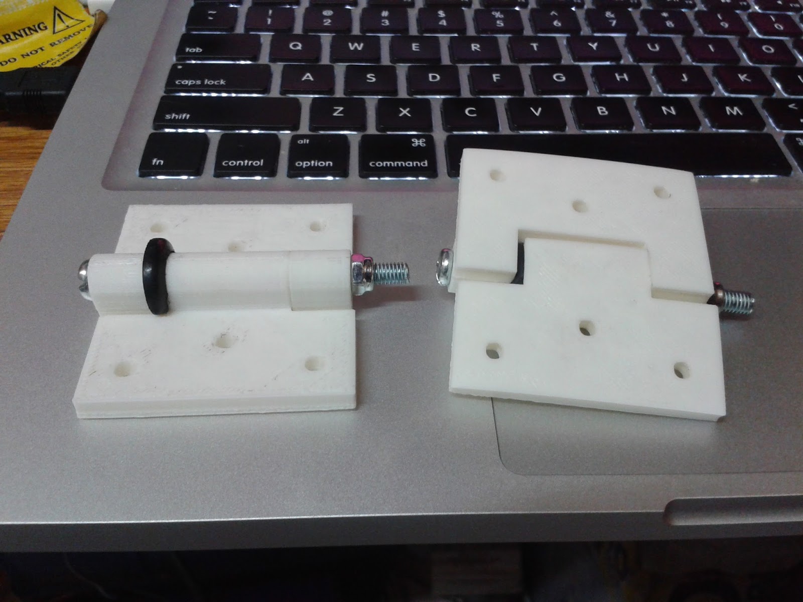
3D printing friction-hinges for the laptop prototype
I have been thinking for a while about what to use for hinges for the MEGA65 laptop prototype. The most important thing is that the hinges need to be friction hinges, like for all sensible laptops. A friction hinge is just a hinge that stays in the same position unless a certain amount of force is applied. For laptops, this means that the screen doesn't slump down under its own weight. Laptops that have bad friction hinges are Not Fun At All To Use. I don't want the MEGA65p prototype to be in that category, so I started looking for friction hinges.
First, I took apart an old mac book pro to see if the friction hinges were useful, but they are tiny, and their small size means that they realistically need a metal chasis to bolt to, in order to spread the forces. Not really an option for me.
Then I looked online at various commercial friction hinges, but they are about $60 a pair, and would take forever to get delivered.
So I searched for 3D-printable friction hinges and found a couple of different designs on thingiverse.com. The one I ended up using is nice and simple, and just uses a rubber o-ring to provide the friction. While the o-ring is likely to wear, it will be pretty easy to replace.

In the process, I also discovered that someone has made a passive digital(!!!) sundial. Yes, a sundial with a digital display, and that is still just a passive lump of stuff, even though it displays the time to the nearest twenty minutes in digital format inside the shadow of the gnomon (the normally pointy bit that makes the shadow on a sundial). I couldn't help myself, so I have one printing at the moment.
First, I took apart an old mac book pro to see if the friction hinges were useful, but they are tiny, and their small size means that they realistically need a metal chasis to bolt to, in order to spread the forces. Not really an option for me.
Then I looked online at various commercial friction hinges, but they are about $60 a pair, and would take forever to get delivered.
So I searched for 3D-printable friction hinges and found a couple of different designs on thingiverse.com. The one I ended up using is nice and simple, and just uses a rubber o-ring to provide the friction. While the o-ring is likely to wear, it will be pretty easy to replace.
In the process, I also discovered that someone has made a passive digital(!!!) sundial. Yes, a sundial with a digital display, and that is still just a passive lump of stuff, even though it displays the time to the nearest twenty minutes in digital format inside the shadow of the gnomon (the normally pointy bit that makes the shadow on a sundial). I couldn't help myself, so I have one printing at the moment.
Photos of laptop prototype work
Last weekend was the Adelaide Maker Faire, so I had a stall with the MEGA65 running from a Nexys4 board, and me attempting to assemble some of the laptop prototype, with rather mixed success.
First, the prototype laptop will likely bear no resemblance to any future production laptop we might make. It is a laptop for me personally to use, although others are free to replicate it. In short, it will be rather big, and rather ugly and imperfect in various ways.
I am also in the middle of some other work, so apologies for the orientation and quality of these shots: I figured that people would still like to see what we have now.
 Here we have the top-half with the screen fitted into using the bezels I made. I measured some things incorrectly, in particular for holding the screen in from behind, so I will need to make some improvements there. The oval hole is for cables to come out to connect into the bottom half until I come up with a better cable routing scheme for it at the back, but that still protects the cables. I will probably have to 3D print some pieces to do that.


Here you can see inside. The panel is held in on the top with entirely the wrong parts, because I really messed up the plans for those. I have now figured I can hold the screen in with two vertical pieces that will pass behind the full-height of the screen, and no get in the way of the inverter (right side on the bottom) or panel driver (left side on the bottom). I also need to make a short VGA cable, because a 2m one won't fit in here with the FPGA board (yes, the "computer" part will be in the "screen", largely because I am using huge batteries :)


Here is the same panel upside-down, so you can see how the drive screws in. The drive also screws to the front-side panel.

And again from on the edge, showing the nice old SONY floppy drive I am using, and the wall-plugs in more detail.

Finally, here is the top side of the bottom case. The two "inside" panels are "ivory" instead of "pearl" because I (incorrectly) thought that I would have to re-do those at some point, but that the outside panels would be fine. I should have done it the other way around, given where all my measurement errors are. Anyway, when I get some time, I will start fixing the problems, and progressively assembling the thing.

First, the prototype laptop will likely bear no resemblance to any future production laptop we might make. It is a laptop for me personally to use, although others are free to replicate it. In short, it will be rather big, and rather ugly and imperfect in various ways.
I am also in the middle of some other work, so apologies for the orientation and quality of these shots: I figured that people would still like to see what we have now.


Here we have the on-screen controls for the panel driver board. This will allow fiddling with video settings. I was quite nicely surprised that I managed to get all 9 holes correctly spaced! The buttons are quite short, so you need finger nails or a pen to operate some of them. I will probably design some 3D printed tops for them at some point to improve this.
You can also see the crenelation around the edges of the pieces here so that they fit together. I just used one of those laser-cut box designers.

Here you can see one corner of the bezel that spaces the screen back 12mm from the font, so that the real C65 keyboard won't touch the screen when it is shut. I got this pretty close, but there were gaps of a couple of millimeters that I need to work out why they appeared. It is possible I put some pieces in the wrong places.

Here you can see inside. The panel is held in on the top with entirely the wrong parts, because I really messed up the plans for those. I have now figured I can hold the screen in with two vertical pieces that will pass behind the full-height of the screen, and no get in the way of the inverter (right side on the bottom) or panel driver (left side on the bottom). I also need to make a short VGA cable, because a 2m one won't fit in here with the FPGA board (yes, the "computer" part will be in the "screen", largely because I am using huge batteries :)

This is the rear of the back of the screen, with the screws holding the inverter and panel driver in. The other four holes are for the FPGA board. They also fit nicely. In fact, I didn't do too bad at all on the top-half for fitting. The bottom-half that has the floppy, keyboard and batteries is a different story altogether...
Here is the bottom and side panels of the bottom. The floppy drive fits great, but I made the hole for it on the right about 20mm too wide, so that needs fixing. The expansion port, video and IEC serial ports and cassette ports on the back are all fine, too, as far as I can tell.
The green pegs are wall plugs which was a nice idea I cam up with to make "pens" for each battery cell. However, I apparently measured them in the middle of the night when I was too tired, because the pens are about 10mm too narrow, and 10mm too short. I can probably drill a few remedial holes and sort that out.
The joystick, power and reset button ports on the left side also fit nicely. However, the mag-safe connector hole turns out to be too close to the back, and doesn't leave enough room for the widget board, so I will need to drill a new 2mm hole in the bottom, and also cut a new side panel. I don't mind redoing the side-panels because I have enough spare plastic for those little bits, but the full-size panels cost $10 - $20 each, depending on whether I can get nice cheap off-cuts from our local plastics shop, Menzel Plastics.

Here is the same panel upside-down, so you can see how the drive screws in. The drive also screws to the front-side panel.

And again from on the edge, showing the nice old SONY floppy drive I am using, and the wall-plugs in more detail.

Finally, here is the top side of the bottom case. The two "inside" panels are "ivory" instead of "pearl" because I (incorrectly) thought that I would have to re-do those at some point, but that the outside panels would be fine. I should have done it the other way around, given where all my measurement errors are. Anyway, when I get some time, I will start fixing the problems, and progressively assembling the thing.

Wednesday, 21 October 2015
MEGA65 @ Amiga30.de - Part 5 - RJ Mical meets the MEGA65 prototype
There isn't too much to say here: RJ Mical meets the MEGA65 prototype and loves it, which naturally makes us all very happy :)
Tuesday, 20 October 2015
Working towards bitplanes and GeoRAM + REU support
Sadly not pretty pictures right now, but I am actively working on fixing the C65-mode bitplanes. This largely consists of making some changes to work out how far the data is getting through the pipeline, resynthesising, and then repeating until I find where the bitplane data is reaching the bit bucket. What I know so far, is that bitplane mode turns on, and that the bitplane complement bits work just fine. It just seems that the bitplane feeders are either not activating when they should, or that they just receive (or just output) all zeroes.
Of course this debug process means I sit around waiting 1 - 2 hours for synthesis sometimes, so in those gaps I am implementing GeoRAM and REU emulation. These turn out to be not that hard to do. GeoRAM is just trivial to implement, because of its super-cheap design. The REU is also fairly easy to implement because its functions are quite easily mapped to the C65's DMAgic. So I am just implementing it as a special front-end to the DMAgic interface in the CPU. The only new feature to add here is the verify mode of the REU, which DMAgic lacks. So it is quite likely that I will have these two RAM expansion controllers working fairly soon -- of course it would then be REALLY nice to have the 128MB DDR2 RAM working, so that they can be usefully used.
In any case, the hypervisor will be able to control the size of each RAM expansion, and point them to the same or different places anywhere in the full 28-bit address space. This means that you will be able to do weird things like point the REU expansion memory to the C64-mode 64KB of RAM, or to colour RAM, or to any other weird location you might choose.
Sunday, 18 October 2015
MEGA65 @ Amiga30.de - Part 4
Okay, so there is now an English translation for the interview with Detlef. I've left it on that page so that it is all still in one place.
Meanwhile, I have done some work towards adding GeoRAM support to the MEGA65, as well as adding some extra debug stuff to make it easier for me to try to track down the long-standing issues with the DDR memory controller. More on those when I am able.
Meanwhile, I have done some work towards adding GeoRAM support to the MEGA65, as well as adding some extra debug stuff to make it easier for me to try to track down the long-standing issues with the DDR memory controller. More on those when I am able.
MEGA65 @ Amiga30.de - Part 3
A quick update: We now have a German transcript of the interview (but not yet the talk) at Amiga30.de. I have attached it to the post with the interview video, so that it is all together. I'll work on an English translation as time permits.
Subscribe to:
Posts (Atom)