
Tonight I am trying to make some progress again on writing to floppies in the MEGA65. Reading has been more or less working for a long time now, but writing has been stuck on the TODO list. I'm now working to fix this.
I have already made a bits_to_mfm.vhdl file that takes a byte and clock byte and from those produces the combined 16 MFM bits that should be written, and writes them out. That module has been tested under simulation, and produces valid bits.
I also pulled that into the development branch of the MEGA65 source, and have bit bitstreams that include it, and in theory, the ability to command the floppy controller to do unformatted track writes for formatting disks. Once I have that working, I'll update the code for writing sectors to do buffered writes at the correct place on the track where the sector should be written. But before we get to that point, let's review how writing to a floppy disk works, and then look at how this is done on a C65, before returning to how I am implementing and testing it on the MEGA65.
How floppies store data
Floppy disks are a form of magnetic media. For our purposes, the important implication of this is that data is stored by writing magnetic field orientation reversals along a track. How those reversals are interpreted depends on the "format" and "encoding" of the disk. Two common challenges for all such encodings are: (1) the disk doesn't spin at a constant or well-callibrated rate, which means that the encoding must be self-synchronising, that is the data clock must be retrievable from the data stream itself; and (2) the magnetic field inversions must not occur more frequently than what we shall call the "magnetic resolution" of the disk and drive.
Early disk encodings were pretty horribly inefficient. For example, Frequency Modulation was an early method that basically wrote clock bits between which the data bits were indicated by whether a magnetic field inversion occurred at the beginning of the bit time frame or in the middle of it.
FM was great in that it ensured that every data bit was cocooned by clock bits on either side of it, thus ensuring the self-synchronising property. However, by inserting those clock bits -- and thus the extra magnetic field reversals -- it means that effectively two field inversions are required for every data bit written, thus causing problems with exceeding the "magnetic resolution" of disks. For this reason, FM data was written at half of the "magnetic resolution" of disks, so that this would not be a problem.
To improve on this situation, Modified Frequency Modulation (MFM) was created that retained the positive properties of FM, but reduced the average rate at which magnetic field inversions were required to only 75% of that required for FM, thus allowing data to be encoded at a higher data rate for a given "magnetic resolution", with each data bit taking up only 1.5 "magnetic bits" of space on average on disk, down from FM's 2. A nice improvement.
Interestingly, the 1541 and 1571 used a substantially more advanced method, Group Code Recording (GCR), which encoded groups of 4 bits using only "5 magnetic bits", i.e., requiring only 1.2 "magnetic bits" per data bit, and without MFM's problem that particular data sequences take up more space than others. This is one of the reasons why the 1541 and 1571 were able to pack more data onto a Double Density 5.25" disk than PCs could at the time, even though these drives used only 35 tracks vs PCs using 40 tracks.
(Another of the reasons was varying the data rate based on the length of the track, so that the data rate more closely tracked the "magnetic resolution" of the disk, which spins at a constant rate, and thus has a higher apparent "magnetic resolution" on the outer tracks, because they are longer, and thus more material passes under the head per unit time).
The 1581, and by implication, the C65's internal 3.5" drive don't use GCR, though. Commodore opted for MFM, presumably because it allowed the use of cheap off-the-shelf floppy controller chips.
An interesting side note is that the Amiga fit more its disks (880KB), not because it used GCR, but because it treated each track as one huge sector, and thus avoided inter-sector gaps (which we will meet again soon), thus allowing increased capacity, at the cost that writing had to be done track at a time, rather than being able to update individual sectors. Had the Amiga also used GCR, the capacity would have been further increased (and some software did such things). If the 1541's GCR scheme were used on the Amiga, then we would have seen the standard disk format there holding 880KB x 1.5 magnetic intervals per bit / 1.2 magnetic intervals per bit = 880KB x 1.25 = 1,100KB, assuming I haven't messed up the maths, or otherwise made an error of fact in the above discussion.
How the C65 Writes to Floppies
So lets look now at how the C65 writes to floppies. The best way to examine this, is to look at the relevant section of the C65 Specifications, which has the following to say about formatting tracks (which is what we care about for now) in section 2.5.3:
Track Writes
Full-track writes can be done, either buffered or unbuffered,
however, the CLOCK pattern register has no buffer, and writes to this
register must be done "one on one".
Write track Buffered
issue "clear buffer" command
write FF hex to clock register
issue "write track buffered" command
write FF hex to data register
wait for first DRQ flag
write A1 hex to data register
write FB hex to clock register
wait for next DRQ flag
write A1 hex to data register
wait for next DRQ flag
write A1 hex to data register
wait for next DRQ flag
write FF hex to clock register
write your first data byte to the data register
you may now use fully buffered operation.
Write Track Unbuffered
write FF hex to clock register
issue "write track unbuffered" command
write FF hex to data register
wait for first DRQ flag
write A1 hex to data register
write FB hex to clock register
wait for next DRQ flag
write A1 hex to data register
wait for next DRQ flag
write A1 hex to data register
wait for next DRQ flag
write FF hex to clock register
loop: write data byte to the data register
check BUSY flag for completion
wait for next DRQ flag
go to loop
Formatting a track
In order to be able to read or write sectored data on a diskette,
the diskette MUST be properly formatted. If, for any reason, marks are
missing or have improper clocks, track, sector, side, or length
information are incorrect, or the CRC bytes are in error, any attempt
to perform a sectored read or write operation will terminate with a
RNF error.
Formatting a track is simply writing a track with a strictly
specified series of bytes. A given track must be divided into an
integer number of sectors, which are 128, 256, 512, or 1024 bytes
long. Each sector must consist of the following information. All
clocks, are FF hex, where not specified. Data and clock values are in
hexadecimal notation. Fill any left-over bytes in the track with 4E
data.
quan data/clock description
---- ---------- -----------
12 00 gap 3*
3 A1/FB Marks
FE Header mark
(track) Track number
(side) Side number
(sector) Sector number
(length) Sector Length (0=128,1=256,2=512,3=1024)
2 (crc) CRC bytes
23 4E gap 2
12 00 gap 2
3 A1/FB Marks
FB Data mark
128,
256,
512, or
1024 00 Data bytes (consistent with length)
2 (crc) CRC bytes
24 4E gap 3*
* you may reduce the size of gap 3 to increase diskette capacity,
however the sizes shown are suggested.
So we can see that we just command the controller to format a track, and then wait for the controller to start asking for bytes, and writing them, together with a clock byte, and it writes them out onto the disk. The clock byte thing is related to what we talked about above about FM using clock bits to provide the self-synchronisation. MFM does something similar, but is able to skip them in certain situations.
The clock byte allows masking of the clock bits after each data bit. Thus using a clock byte of $FF means that normal data will be written. If a different value is used, then some clock bits will be missing, which would normally cause problems. But MFM disk formatting normally uses a special data byte written with a different clock as a synchronisation marker, to help know where to start decoding data. The convention is to use data byte $A1 written with clock byte $FB, i.e., the byte $A1 written with one missing clock bit. This combination results in an on-disk sequence of magnetic field inversions that can never happen as part of normal data, thus allowing it to safely provide the synchronisation function.
MEGA65 Floppy Controller
This is all handled by the F011 floppy controller on the C65. On the MEGA65, it is part of the MEGA65's enhanced F011 functionality that lives in the SD card controller (so that the SD card can be used to emulate floppy disks for the MEGA65).
The F011 controller has, among others, a command register, a data register and a clock register. Various commands such as read a sector, write a sector or format a track can be issued to the command register. In the case of the "format a track" command, we implement behaviour almost identical to that of the C65, i.e., we simply start writing magnetic field inversions to the floppy, based on clock and data bytes provided by the respective registers.
The lowest later of this is done in the bits_to_mfm.vhdl file, which basically takes in a data byte and clock byte, and writes out valid magnetic field inversion signals to the floppy drive based on those. That module has already been tested.
Current work
The current coal face of work lies at tying this into the overall controller, and the connection to the real floppy drive interface hardware. I have connected the logic together, and started writing a test program, https://github.com/MEGA65/mega65-tools/blob/master/src/tests/floppytest.c, that attempts to write to a track, and gives me various bits of debug output to see what is going on.
To properly test this, I also need to see what is happening on the floppy drive's WGATE line, which is the "write gate", i.e, "write enable" line, and WDATA, which is the "write data" line. Whenever the WDATA line is toggled from high to low, or low to high, it causes a magnetic field inversion to be written to the disk.
To monitor those lines, I need access to pins 22 (WDATA) and 24 (WGATE) on the floppy cable interface. The easiest way for me to access those was to put an old dual floppy drive cable in my MEGA65, so that I have a spare connector on the cable that I can tap into with probes:

Using this method of probing, I can see, for example, the index hole pulses on the SYNC line, occurring every 200ms or so (300rpm = 5 revolutions per second = 200ms per revolution):

Looking at the WDATA line, I saw that our pulses are only ~50ns wide, though, which is probably too narrow:
According to Figure 7 of this datasheet, the pulses should instead be half the width of each "magnetic bit" on disk. So I will modify this in the VHDL, and resynthesise, and revisit in the morning.
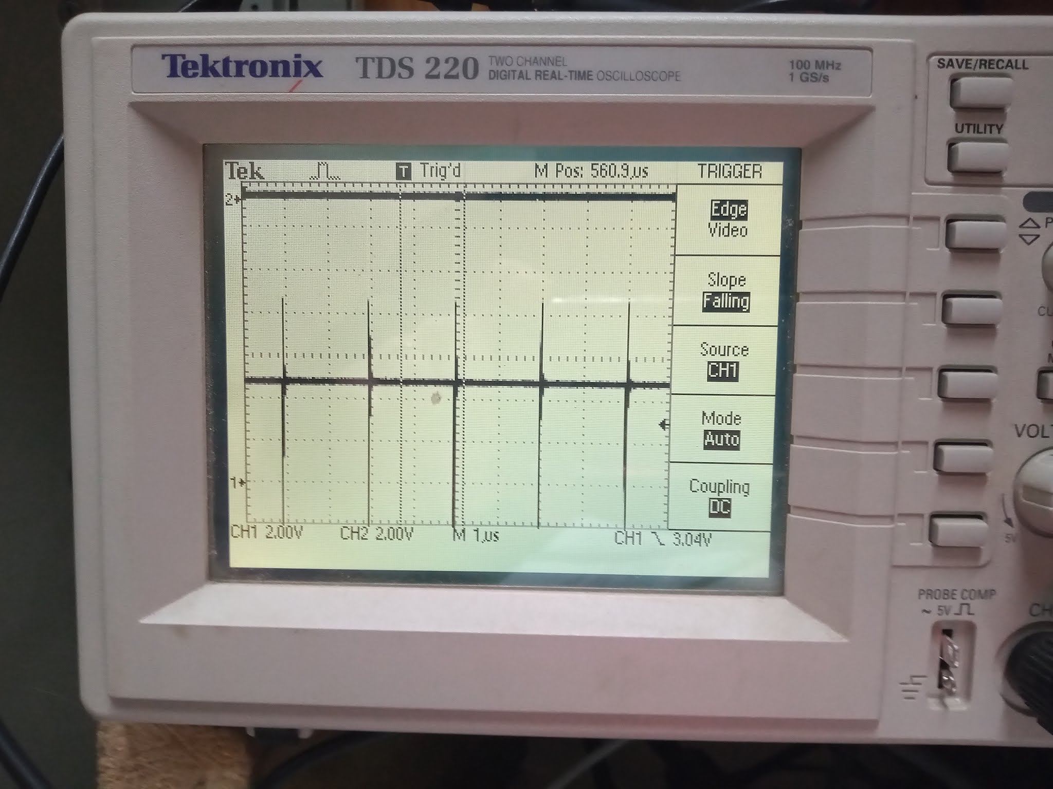
Well, its now tomorrow morning, well tomorrow evening, really. The bitstream has synthesised, so I can see if I have fixed the pulse-widths:

Much better :) The spiking at the edges of the clock pulses is just because of the very fast edges, relatively high voltage (5V) and long oscilloscope probes. This should not be problematic for actual operation, however.
So now I need to see if the WGATE line is getting pulsed low when it starts writing... And, yes, after attaching a 2nd probe so that I can watch both WDATA (top) and WGATE (bottom) at the same time, we can see that the idle pulse train changes once the WGATE line is pulled low:

So, this is all looking good right now. Probably the next step is for me to improve the floppytest.c programme, to actually write an entire track with 10 sectors worth of data, and see if it is readable back as real sectors. I'll be pleasantly surprised if I get that right first time. Preparing for the likely situation that I won't get it right, I'll start having a think about how I can efficiently and reliably read a full track of data from the drive, so that I can see exactly what I have written.
But first, lets go through the process of writing the track, which consists of:
1. Write 12 gap bytes (data=$00, clock=$FF)
Then for each of the 10 sectors on the track:
2. Write three mark (sync) bytes (data=$A1, clock=$FB)
3. Write Header marker (data=$FE, clock=$FF)4. Write Track number (data=<track number>, clock=$FF)
5. Write Side number (data=<side number>, clock=$FF)
6. Write sector number (data=<sector number>, clock=$FF)
7. Write sector length (data=$02 (meaning 512 bytes), clock=$FF)
8. Write header CRC byte 0 (data=<crc byte>, clock=$FF)
9. Write header CRC byte 1 (data=<crc byte>, clock=$FF)
10. Write 23 gap bytes (data=$4E, clock=$FF)
11. Write 12 gap bytes (data=$00, clock=$FF)
12. Write three mark bytes (data=$A1, clock=$FB)
13. Write Data Marker (data=$FB, clock=$FF)
14. Write 512 data bytes (data=$00, clock=$FF)
15. Write data CRC byte 0 (data=<crc byte>, clock=$FF)
16. Write data CRC byte 1 (data=<crc byte>, clock=$FF)
17. Write 24 gap bytes (data=$4E, clock=$FF)
After which, we have written the whole track.
But before we can do this, we have to work out how to correctly calculate the CRC values.
Well, actually, the CRC value can wait just a little while, while I first confirm if any data is being written to the track. This leads us down the path of working out how to easily read a track of raw data from the MEGA65. Presently we don't have an automated way to do this, unlike on the Amiga that natively handles floppy data at the raw magnetic level. What we do have is a register that provides us with the quantised MFM gap size data, i.e., whether the MFM decoder thinks it has seen a short, medium or long gap between magnetic flux inversions. That is sufficient to decode an MFM-formatted track, as is the case with what we need.
However, this is just a bare unbuffered register, which means that we need to have a tight loop that samples it, and writes the successive values out into memory. As short gaps can occur at a rate of up to 500KHz, this means the loop must take less than 80 cycles per value read. I tried doing this in C, but CC65 generates code that is a bit too big and slow, so I will need to make an assembly routine to do this. It won't be complicated, however. Basically we have to check if we have reached the end of the track (negative edge of index sensor, in bit 7 of $D6A0), and save every different value that appears on $D6AC, which contains the quantised gap information, as well as a counter so we know if we have missed any gaps, and whether the MFM decoder has detected a SYNC byte.
So something like this should do the trick:
_readtrackgaps:SEI
;; Backup some ZP space for our 32-bit pointer
LDX #$00
save:
LDA $FA,X
STA temp,X
INX
CPX #4
BNE save
;; Initialise 32-bit ZP pointer to bank 5 ($50000)
LDA #$00
STA $FA
STA $FB
STA $FD
LDA #$05
STA $FC
waitforindexhigh:
LDX $D6A0
BPL waitforindexhigh
waitforfirstindexedge:
LDX $D6A0
BMI waitforfirstindexedge
;; Pre-load value of $D6AC so we can wait for it to change
LDA $D6AC
STA $FF
loop:
waitfornextfluxevent:
LDA $D6AC
CMP $FF
BEQ waitfornextfluxevent
INC $D020
;; Store byte in bank 5
;; STA [$FA],Z
.byte $EA,$92,$FA ; STA [$FA],Z to save value
STA $FF ; Update comparison value
;; Show some activity while doing it
.byte $9C,$10,$C0 ; STZ $C010
LDY $FB
STA $C012
;; Are we done yet?
;; INZ
.byte $1B ; INZ
BNE loop
INC $FB
LDY $FB
BNE loop
done:
;; Done reading track or we already filled 64KB
LDX #$00
restore:
LDA temp,X
STA $FA,X
INX
CPX #4
BNE restore
CLI
RTS
temp: .byte 0,0,0,0
That should be less than 50 cycles per loop, so is probably even just about fast enough to also handle HD disks, but that's not our concern right now.
With that routine in place, I can now read raw data from the disk, which looks like this:
00000000: e7 eb e8 ec f0 f6 f8 fc 00 04 08 0c 10 14 18 1c
00000010: 20 24 28 2c 30 34 38 3c 40 44 48 4c 50 54 58 5c 00000020: 60 64 68 6c 70 74 78 7c 80 84 88 8c 90 94 98 9c
00000030: a0 a4 a8 ac b0 b4 b8 bc c0 c4 c8 cc d0 d4 d8 dc
00000040: e0 e4 e8 ec f0 f4 f8 fc 00 04 08 0c 10 14 18 1c
00000050: 20 24 28 2c 30 34 38 3c 40 44 48 4c 50 54 58 5c 00000060: 60 64 68 6d 72 75 76 7a 7d 80 86 89 8e 91 94 9a
00000070: 9d a2 a5 a8 ac b0 b4 b8 bc c3 c7 c4 c8 cc d0 d7
00000080: db df e3 e4 e8 ef f3 f4 f8 ff 03 00 04 08 0f 13
00000090: 14 18 1f 23 24 28 2f 33 34 38 3f 43 44 48 4f 53
000000a0: 54 58 5f 63 64 68 6f 73 74 78 7f 83 84 88 8f 93
000000b0: 94 98 9f a3 a4 a8 af b3 b4 b8 bf c3 c4 c8 cb cf
Only the bottom 2 bits of each byte are MFM data, the remaining six bits are the counter that is used to tell when the next set of bottom 2 bits are available for reading. In the process of doing this, I realised that the SYNC byte detection reporting in this register was broken, and am synthesising a fix for that. However, in the meantime, it should be possible to analyse the data that we have, to see what we have, and if it looks like data is being written properly or not.
With 64KB of data, we should around 64Kbit of data, i.e., around 8KB, or about 3/4 of a complete track. When it run, it seemed to take longer than the 200ms that a single rotation of the floppy would imply, so I want to try to figure out what is going on there, and in particular, if any gaps are being missed, which I can check with the upper bits that contain the counter.
I already have a utility for decoding raw MFM streams into bytes and sync values in mega65-tools:src/tests/mfm-decode.c, however it doesn't expect pre-quantised gaps. However, it shouldn't be too hard to modify it to support this.
In the process of doing that, I realised that the gap size sometimes gets updated between gap count updates which was resulting in somewhat messed up data. I'm synthesising a fix to the VHDL for that problem now, but will continue trying to get the MFM decoder utility working on the data in the meantime.
It turns out that this problem with changing values is noticed for over 3% of all values. This is probably enough to completely mess up the captured data in terms of decoding it. So time to wait for the synthesis to run, or do a really low-level flux capture via $D6A0, which allows reading of the raw floppy RDATA line. That involves reading that line via DMA, thus resulting in 20,250,000 samples per second, or about 65536/20250000 = ~1.6% of a track's worth of data. (This is why I made the $D6AC capture method to begin with).
Although only 1.6% of a track is not much, its probably still helpful for revealing what we are doing with the writing, and what particular error modes we are inducing in the written data, if any, since they are likely to be at the bit and byte level. Thinking more about it, it should also be possible to switch the CPU to 1MHz mode or 2MHz mode, which also slows down DMA jobs, to capture more of a track.
In any case, I need to try something, as the $D6AC capture method seems to be quite unreliable, and reading even a valid track is resulting in gibberish -- or alternatively, the quantised gaps have a different meaning than expected. That said, it seems to detect the SYNC bytes without great trouble, which means that the 1.5x and 2.0x gap lengths must be okay.
Sampling $D6A0 at 1MHz or even 3.5MHz seems to also be problematic, because the pulses on the read line of the floppy drive seem to be very narrow, with most resolving to only a single sample at 3.5MHz. Reading the data sheet for a TEAC 3.5" floppy drive, apparently the RDATA line can go low for as little as 0.15 microseconds, which is much too narrow to be reliably detected at 3.5MHz when doing a DMA copy, which results in a 3.5MHz / 2 = ~1.75MHz = ~0.57 usec effective minimum pulse width, given that it takes one read and one write cycle for each byte copied. So back to the drawing board yet again.
In short, any adequate sample rate will result in an inacceptably short capture length. So back to using $D6AC. That register does have a sister register that lets us get the unquantised length, so I might modify the routine I made to read the actual length, instead of the quantised length, and see if that produces any more sensible data.
After a bit of fiddling, I am now confident that I am reading the flux transitions correctly, and without any gaps, as $D699/$D69A also includes a counter in the upper 4 bits, which I check on the captured data for any skipped values. There are no skipped values, so we can be pretty sure that we are collecting all of the flux transitions, and getting the number of 40.5MHz clock cycles between them.
Feeding this into my mfm-decode.c programme, which I have now enhanced to support capture files in this format, I see the SYNC bytes being correctly parsed out, e.g.:
...
gap=2.0 (325)
gap=1.5 (245)
gap=2.0 (327)
gap=1.5 (242)
Sync $A1
gap=1.0 (165)
gap=2.0 (318)
gap=1.5 (244)
gap=2.0 (322)
gap=1.5 (240)
Sync $A1
gap=1.0 (167)
gap=2.0 (327)
gap=1.5 (244)
gap=2.0 (324)
gap=1.5 (245)
Sync $A1
gap=1.0 (163)
gap=1.0 (161)
gap=1.0 (159)
gap=1.0 (157)
gap=1.0 (162)
...
However, I am not getting particularly sensible byte data. I am seeing some short runs of bytes between SYNC bytes, and then longer slabs of bytes, which looks like the general structure of sector headers and sector bodies. However, the number of bytes being output are quite wrong, e.g., 1,616 bytes for a sector that should have 512 bytes. To avoid it being my badly formatted data that is the problem here, I am reading track 38 on a disk that was formatted in another machine.
One part of the mystery that worries me is the gaps of length 1.0 in the SYNC bytes. They should just be 2.0, 1.5, 2.0, 1.5 for each SYNC byte, with no extra flux transition in between, if I understand things correctly.
But the bigger concern for now, is that we are seeing reported gaps between magnetic flux inversions that are _very_ long, e.g.:
Sync $A1
gap=1.0 (160)
gap=1.0 (157)
gap=1.0 (159)
gap=1.0 (167)
gap=2.1 (348)
gap=0.9 (140)
gap=25.3 (4095)
This gap of 4095 cycles should never happen. In fact, 4095 is the largest it can report, so it is possible that it is in fact reporting 65535 cycles or longer.
The only cause I can think of here, is that the head was still stepping between tracks, or the WGATE was still open or something like that. But even that doesn't explain why it detected the SYNC bytes immediately before hand. The head certainly isn't stepping, because I trigger the track read on a key press in a busy loop. So several seconds have typically elapsed since the last head track. And if the WGATE was still open, then we wouldn't read anything, and thus we shouldn't expect to see the SYNC bytes -- but we do see them, and the correct number of them.
Also adding to the mystery, the timing of the flux inversions for the SYNC bytes are quite accurate, to within 10% or so of the expected time, but the data following those is then all over the shop, in terms of the gap lengths. But it is also very common to see gap lengths of 3.0x, which is very weird, as we should be seeing 1.0x, 1.5x and 2.0x, as we do in the SYNC bytes.
If I didn't know better, I would suspect that this disk has a messed up track 38. So to eliminate that possibility, I am running a full disk read test on it using the MEGA65. That is, using the same MFM decoder implementation that is turning up these funny gap lengths. Maybe it will turn out that the disk is more messed up than I suspect... and it looks like that may well be the case:

So maybe I should be trying to read from track 0 for my MFM testing, since that track seems to be good...
Ah, that's much better, and I am indeed seeing correct sector structures:
...
$4e $4e $4e $4e $4e $4e $4e $4e $4e $4e $4e $4e $4e $4e $4e $4e
$4e $4e $4e $4e $4e $4e $4e $4e $4e $4e $4e $4e $51 $39 $39 $39 $39
$39 $39 $39 $39 $39 $39 $39 $39 $39 $39 $39 $39 $39 $39 $39 $39 $39
$39 $39 $39 $39 $39 $39 $39 $39 $39 $39 $38 $00 $00 $00 $00 $00 $00
$00 $00 $00 $00 $00 $02
(73 bytes since last sync)
Sync $A1
Sync $A1
Sync $A1
$fe $00 $00 $01 $02 $ca $6f $4e $4e $4e $4e $4e $4e $4e $4e $4e
$4e $4e $4e $4e $4e $4e $4e $4e $4e $4e $4e $4e $4e $00 $00 $00 $00
$00 $00 $00 $00 $00 $00 $00 $00
(41 bytes since last sync)
Sync $A1
Sync $A1
Sync $A1
$fb $00 $00 $00 $00 $00 $00 $00 $00 $00 $00 $00 $00 $00 $00 $00
$00 $00 $00 $00 $00 $00 $00 $00 $00 $00 $00 $00 $00 $00 $00 $00 $00
$00 $00 $00 $00 $00 $00 $00 $00 $00 $00 $00 $00 $00 $00 $00 $00 $00
...
$00 $00 $00 $00 $00 $00 $00 $00 $00 $00 $00 $00 $00 $00 $00 $00 $00
$00 $00 $00 $00 $00 $00 $00 $00 $00 $00 $00 $00 $00 $00 $00 $00 $00
$00 $00 $00 $00 $da $6e $4e $4e $4e $4e $4e $4e $4e $4e $4e $4e $4e
$4e $4e $4e $4e $4e $4e $4e $4e $4e $4e $4e $4e $4e $4e $4e $4e $4e
$4e $4e $4e $4e $4e $4e $4e $00 $00 $00 $00 $00 $00 $00 $00 $00 $00
$00 $00
(562 bytes since last sync)
And the capture completes faster, and actually reads several complete sectors, in accordance with expectation.
So after all that chasing my tail, I now have a nice reliable way to read multiple sectors from a track, if not quite the entire track, and then to decode it to see what is actually there.
Now to try to read the track that I have attempted to format, and see what we see there, and where it looks sensible or not. I know the CRC bytes will still be wrong, but we should, in theory at least, see the SYNC bytes and other bytes.
The SYNC bytes are indeed visible, but the rest of the data is rubbish, like this:
Sync $A1
Sync $A1
Sync $A1
$fd $7a $ab $ae $ba $eb $ae $ba $eb $ae $ba $eb $ae $ba $eb $ae
$ba $eb $ae $bb
(20 bytes since last sync)
Sync $A1
Sync $A1
Sync $A1
$f6 $ba $eb $ae $ba $eb $ae $ba $eb $ae $ba $eb $ae $ba $eb $ae
$ba $eb $b4
(19 bytes since last sync)
Sync $A1
Looking closer, I realised I was setting the MFM clock byte to the data value, and the MFM clock value in the MFM data byte. Naturally this will result in a garbled mess. After fixing that and a few other little bits and pieces, its now looking _much_ better:
Sync $A1
Sync $A1
Sync $A1
$fe $27 $00 $01 $02 $00 $00 $4e $4e $4e $4e $4e $4e $4e $4e $4e
$4e $4e $4e $4e $4e $4e $4e $4e $4e $4e $4e $4e $4e $4e $00 $00 $00
$00 $00 $00 $00 $00 $00 $00 $00 $00
(42 bytes since last sync)
Sync $A1
Sync $A1
Sync $A1
$fb $00 $00 $00 $00 $00 $00 $00 $00 $00 $00 $00 $00 $00 $00 $00
$00 $00 $00 $00 $00 $00 $00 $00 $00 $00 $00 $00 $00 $00 $00 $00 $00
$00 $00 $00 $00 $00 $00 $00 $00 $00 $00 $00 $00 $00 $00 $00 $00 $00
...
$00 $00 $00 $00 $00 $00 $00 $00 $00 $00 $00 $00 $00 $00 $00 $00 $00
$00 $00 $00 $00 $00 $00 $00 $00 $00 $00 $00 $00 $00 $00 $00 $00 $00
$00 $00 $00 $00 $4e $4e $4e $4e $4e $4e $4e $4e $4e $4e $4e $4e $4e
$4e $4e $4e $4e $4e $4e $4e $4e $4e $4e
(536 bytes since last sync)
Sync $A1
Sync $A1
Sync $A1
$fe $27 $00 $02 $02 $00 $00 $4e $4e $4e $4e $4e $4e $4e $4e $4e
$4e $4e $4e $4e $4e $4e $4e $4e $4e $4e $4e $4e $4e $4e $00 $00 $00
$00 $00 $00 $00 $00 $00 $00 $00 $00
(42 bytes since last sync)
Sync $A1
Sync $A1
Sync $A1
$fb $00 $00 $00 $00 $00 $00 $00 $00 $00 $00 $00 $00 $00 $00 $00
$00 $00 $00 $00 $00 $00 $00 $00 $00 $00 $00 $00 $00 $00 $00 $00 $00
...
In short, we are writing essentially valid data, just with incorrect checksum bytes. Yay!
(There is another minor wrinkle I have to sort out at some point, which is that I need to be bug-compatible with the MFM clock byte latching behaviour of the C65's floppy controller, which basically doesn't latch at all, thus allowing the clock byte to be changed after setting the value of the byte to write. But I'll worry about that when I have the rest of the formatting system working, and producing valid tracks from my test programme. The bug compatibility is required so that the C65 DOS ROM routines will work to format disks. I'll also have to make the format command disable the auto-tracking feature, so that the head doesn't accidentally seek while writing.)
The checksum algorithm for floppy sectors is not too bad, but I do hate writing CRC code, because it is a bit fiddly. Basically to do it properly, you have to make a test harness with a bunch of known correct inputs and outputs, and verify that it is indeed doing what it should. Then the fun comes when it doesn't produce correct output, and you have to work out what minor (or major) detail you have wrong. But that can wait for another day, because I'm going to go to bed happy now, knowing that I can write bytes to the disk.
neat. :3
ReplyDeleteI really enjoying reading these posts. Its so refreshing.
ReplyDelete