Bitplanes are now mostly working, although we are still tracking down some remaining bugs with V400 mode, and some bitplanes being shifted by 16 pixels.
The next challenge is to implement the VIC-III Display Address Translator (DAT). This is a little piece of logic in the VIC-III that makes it easier to modify pixels in the bitplanes. Basically you provide it an X and Y coordinate, and it maps the corresponding bytes of the bitplanes to $D040-$D047, so that they can be manipulated, without having to do any crazy arithmetic to find them. This makes the bitplanes on the C65 less cumbersome than they would have otherwise been. This is how the C65 specifications document describes the DAT:
Display Address Translator (DAT)
The C4567R6 contains a special piece of hardware, known as the
Display Address Translator, or DAT, which allows the programmer to
access the bitplanes directly. In the old VIC configuration, the
bitmap was organized as 25 rows of 40 stacks of 8 sequential bytes.
This is great for displaying 8 x 8 characters, but difficult for
displaying graphics.
The DAT overcomes the original burden by allowing the programmer
to specify the (X,Y) location of the byte of bitplane memory to be
read, modified, or written. This is done by writing the (X,Y)
coordinates to the BPX and BPY register, respectively. The user can
then read, modify, or write the specified location by reading,
modifying, or writing one of the eight Bitplane registers. There is
one bitplane register for each bitplane.
The DAT automatically determines whether to use 320 or 640 pixel
mode, and whether to use 200 or 400 line mode. It will also use the
areas specified for the bitplanes, using the Bitplane Address
registers.
Anyway, that is the purpose of the DAT, how it is implemented is rather interesting. The C65 specifications document tells us, somewhat cryptically:
DAT -- Display Address Translation
Display Address Translation, or DAT fetches, are not actually
DMA-type accesses, but rather CPU address redirections to RAM. In this
case, the unmultiplexed address bus is totally separated from the
multiplexed address bus.
That is, it suggests that the VIC-III somehow causes the target address to be re-written, when the CPU accesses $D040-$D047. To better understand what is going on here, one has to understand how the VIC-III is the gate-keeper of all RAM accesses on the C65. While the 4502 is an 8-bit processor, the VIC-III is a partly 16-bit graphics chip. More specifically, it has two 8-bit wide data buses, D and E, each of which is normally attached to 64KB of RAM. In order to have enough bandwidth for the bitplane modes, it can simultaneously fetch from both the D and E buses. Because it uses DRAM, and also looks after the CAS/RAS selection, the whole process is somewhat complicated.
However, as the DAT fetch description above describes, it is possible for the VIC-III to completely substitute the address that the CPU provides, for one that it has provided internally. This indeed works very nicely to allow the DAT to be a very simple piece of hardware in the VIC-III.
So, now the question is how to implement the DAT on the MEGA65. We don't have this bus arrangement on the MEGA65: The CPU has direct access to memory. Thus we can't implement the DAT solely in the VIC-III. The CPU itself does have memory address re-writing capability, however, so we could implement it there.
The question then becomes whether to calculate the bitplane addresses and offsets in the VIC-III, and export them to the CPU, or to calculate them in the CPU, which means the CPU has to sniff VIC-III/IV register writes, in order to know what mode we are in, and where the bitplanes are located in memory.
It is probably simpler and safer to export the bitplane start addresses and video mode flags to the CPU, and have it do the address computation on those. This requires 8 bitplanes x 3 address bits per bitplane = 24 bits of address information, plus the H640 and V400 flags. In reality, we need 2x24 bits of address, because the 400 pixel high modes are interlaced, and pull data from two separate sources in that mode. In both cases, the CPU then needs to calculate INT(Y/8)*(320/8*8)+ (Y and 7)+INT(X/8)*8 + bitplane start address for 320x200 bitplanes. For the V400 modes with interlace, we need to use Y/2 instead of Y, and to use the bottom bit of Y to pick the odd or even bitplane address. For the H640 modes, we simply change the 320/8*8 to 640/8*8.
I could have written those as simply 320 or 640 instead, however, I wanted to make transparent that the addresses are based on C64-style bitmap addressing, where each 8x8 character-sized cell is formed from 8 bytes. Thus the pixel at (0,0) (measured from the top-left of screen) will be in byte 0, while the pixel at (8,0) will be in byte 8, because after every 8 pixels in the X direction, you have to skip 8 bytes, not one, because you are moving to the next character cell. If that sounds confusing, search for a tutorial on the C64 bitmap mode.
So, taking all off that into account, this means that the CPU needs to look at the DAT X and Y positions, H640 and V400, and from those, it can calculate the offset into a bitplane, and whether it is the odd or even bitplane as the source. We really want to avoid multiplication by big numbers in the CPU, so we can instead calculate the bitplane offset as:
offset = INT(Y/8)*256 + INT(Y/8)*64+ (Y and 7) + INT(X/8)*8
While we still have some divides and multiplies here, they are all powers of two, so can be done by simply shifting bits left and right as required.
As is often the case, by explaining something, it is possible to find improvements. Whereas I had previously figured I would need to sniff the DAT X and Y positions, I can instead calculate those in the VIC-IV, and export only the bitplane offset and odd/even flag to the CPU, together with the bitplane addresses. Then the CPU will know all that it needs to, in order to redirect memory accesses to $D040-$D047 to the appropriate place in the bitplanes.
Now that I have thought out how I can implement the DAT, I have added it to my list of tasks.

Making a C64/C65 compatible computer
Sunday, 24 December 2017

Saturday, 23 December 2017
Fixing IRQ following BRK / BoulderMark score = 102x stock C64
The BRK instruction on the 6502 is effectively just a software-triggered IRQ. The only difference is that a special bit gets set in the processor flags when pushed on the stack, and that BRK increments the program counter by two.
I had been seeing a problem for a while now, where some instructions would not work reliably. I thought that I had a bug in the branch instructions, but it turns out the problem was in BRK, which is used in the Lorenz test programs for branches, to find out where the address a branch has gone to. Basically these tests would sometimes fail. But only sometimes. Intermittent bugs can be a real pain, and this was no exception.
First, I instrumented the Lorenz test program for BNE to report the expected and actual branch address, and then to infinite loop in the test. I noticed that it was always 2 bytes later than expected. My first guess was that the program counter was being mistakenly incremented during a branch instruction under some special condition. By accident, I discovered that it was dependent on an IRQ occuring.
This really was a piece of luck, as I had disabled IRQs on a Nexys4 MEGA65, so that I could single-step without always ending up in the IRQ routine. I found that I couldn't make the problem occur in that mode, even if I set the CPU free running at 50MHz overnight.
This was a major clue to tracking down the problem, although I still thought the problem was in the branch instruction not setting some program counter control flag correctly. But then I remembered that BRK is a software interrupt, and if it got tangled up with a real IRQ, and I wasn't handling things properly, then things could go bad, in exactly the way that I was seeing.
So, after having bashed my head against this bug on and off for a few months, it tool two lines of VHDL, to make sure that an IRQ could never get confused with a BRK instruction.
What was particularly strange about this bug in the end, is that I had noticed that at some point along the line the BoulderMark benchmark for the C64 had stopped working. This is part of what made me suspect it was the branch instructions, as I could see that faulty branching could certainly make things crash -- although why it should only happen in some programs and not others was a mystery.
Now, the situation has been turned on its head: I have fixed the BRK instruction's interaction with IRQs, and not modified the operation of any other instruction, and suddenly BoulderMark is working again -- even though I have confirmed that it never uses BRK anywhere. It is a bit dissatisfying, actually, to not know exactly why this has fixed BoulderMark, as it leaves a niggly fear that there might be some other subtle bug lurking still in all this. But, for now I am just happy that BoulderMark runs again. While the few changes to the CPU since it was last working stably have been relatively minor, it was still nice to see that the MEGA65 has now ticked over to yielding a BoulderMark score that is >100x that of a stock C64, as you can see below.

I had been seeing a problem for a while now, where some instructions would not work reliably. I thought that I had a bug in the branch instructions, but it turns out the problem was in BRK, which is used in the Lorenz test programs for branches, to find out where the address a branch has gone to. Basically these tests would sometimes fail. But only sometimes. Intermittent bugs can be a real pain, and this was no exception.
First, I instrumented the Lorenz test program for BNE to report the expected and actual branch address, and then to infinite loop in the test. I noticed that it was always 2 bytes later than expected. My first guess was that the program counter was being mistakenly incremented during a branch instruction under some special condition. By accident, I discovered that it was dependent on an IRQ occuring.
This really was a piece of luck, as I had disabled IRQs on a Nexys4 MEGA65, so that I could single-step without always ending up in the IRQ routine. I found that I couldn't make the problem occur in that mode, even if I set the CPU free running at 50MHz overnight.
This was a major clue to tracking down the problem, although I still thought the problem was in the branch instruction not setting some program counter control flag correctly. But then I remembered that BRK is a software interrupt, and if it got tangled up with a real IRQ, and I wasn't handling things properly, then things could go bad, in exactly the way that I was seeing.
So, after having bashed my head against this bug on and off for a few months, it tool two lines of VHDL, to make sure that an IRQ could never get confused with a BRK instruction.
What was particularly strange about this bug in the end, is that I had noticed that at some point along the line the BoulderMark benchmark for the C64 had stopped working. This is part of what made me suspect it was the branch instructions, as I could see that faulty branching could certainly make things crash -- although why it should only happen in some programs and not others was a mystery.
Now, the situation has been turned on its head: I have fixed the BRK instruction's interaction with IRQs, and not modified the operation of any other instruction, and suddenly BoulderMark is working again -- even though I have confirmed that it never uses BRK anywhere. It is a bit dissatisfying, actually, to not know exactly why this has fixed BoulderMark, as it leaves a niggly fear that there might be some other subtle bug lurking still in all this. But, for now I am just happy that BoulderMark runs again. While the few changes to the CPU since it was last working stably have been relatively minor, it was still nice to see that the MEGA65 has now ticked over to yielding a BoulderMark score that is >100x that of a stock C64, as you can see below.

Friday, 22 December 2017
Automatic VIC-II Compatibility Regression Testing - Part 1
One of the challenges of implementing the MEGA65 is to be sure that we have compatibility with the VIC-II and other custom chips in the C64. This gets more complex as we fix bugs and add missing functions, as we might accidentally introduce a regression.
This is of course why test cases are very useful, and there are a bunch of test cases as part of the excellent VICE emulator suite. However, from the ones I have looked at, they are rather specialised, and there is no trivial way to run them all, and get informed when one or more of them fails. (It is possible that I have the wrong end of the stick here, and that this can be done with VICE, and I would welcome correction on this point.)
I have decided to fix this state of affairs, and write a single program that runs through a large number of function and compatibility tests, and provides meaningful failure messages, so that whenever we build a bitstream, we can check to make sure that nothing has gone backwards.
My expectation is that this program will grow in fits and starts according to our needs, and may end up being a set of automatically chaining test programs, similar to the 6502 test suite for the C64, that has programs that test a specific instruction, and then load the test for the next instruction when done.
Anyway, I have begun implementing the first tests to help track down a problem with sprite positioning in the new 800x600 video modes. It starts by checking sprite to sprite collision and then sprite-to-character collision, in such a way that it can work out where sprites are being drawn,relative to the text display.
The program purposely is C64 compatible, so that I can make sure that the tests run the same on a real machine (or in VICE for the simpler stuff, until I get an SD-IEC or Ultimate 1541). Here is what it looks like running in VICE so far:
 The test that fails might actually be wrong -- I am currently researching to find out of a real C64 detects sprite collisions that happen behind the borders. My gut feeling is that it probably does, but I am not yet sure.
Anyway, it is a starting point, and I will post an update when it is somewhat more matured.
This is of course why test cases are very useful, and there are a bunch of test cases as part of the excellent VICE emulator suite. However, from the ones I have looked at, they are rather specialised, and there is no trivial way to run them all, and get informed when one or more of them fails. (It is possible that I have the wrong end of the stick here, and that this can be done with VICE, and I would welcome correction on this point.)
I have decided to fix this state of affairs, and write a single program that runs through a large number of function and compatibility tests, and provides meaningful failure messages, so that whenever we build a bitstream, we can check to make sure that nothing has gone backwards.
My expectation is that this program will grow in fits and starts according to our needs, and may end up being a set of automatically chaining test programs, similar to the 6502 test suite for the C64, that has programs that test a specific instruction, and then load the test for the next instruction when done.
Anyway, I have begun implementing the first tests to help track down a problem with sprite positioning in the new 800x600 video modes. It starts by checking sprite to sprite collision and then sprite-to-character collision, in such a way that it can work out where sprites are being drawn,relative to the text display.
The program purposely is C64 compatible, so that I can make sure that the tests run the same on a real machine (or in VICE for the simpler stuff, until I get an SD-IEC or Ultimate 1541). Here is what it looks like running in VICE so far:

Anyway, it is a starting point, and I will post an update when it is somewhat more matured.
Thursday, 21 December 2017
Instruction-Level Timing Accuracy is here
It is summer time here in Australia, which means that it is time for holidays for me. For those of you reading from the Northern Hemisphere, the idea of Christmas in summer may sound crazy. However, I can assure you that this is not the case. It is in fact COMPLETELY INSANE. You have all the rush of Christmas, which should be happening when the weather outside is horrible, and the days short and dark, instead happening just when you really want to be going on holidays instead. So 1/3 of our summer (seasons start on the 1st down here rather than the 21st because of the lower thermal mass of the Southern Hemisphere due to the lack of large continents) disappears into the stress of Christmas, including several days of food-induced coma caused by trying to sustain our European traditions of having a big hot meal for Christmas, even though it might be 42C outside. Then, come late June, when our weather is at its worst (but this is Australia, so it just means 8 hours of day light, and daytime temperatures around 10C, and nights as cold as 3C. We do however get some pretty nasty wind courtesy of the same lack of large land masses in this half of the world), we have not even a single public/bank holiday for almost four months.
Anyway, we nonetheless survive, and it means I have some time to potter away on finishing off the core functionality of the MEGA65. Thus, there will hopefully be a number of posts over the next few weeks, before I have to dive head-long back into work.
What I have been working on the last few days is getting the new video modes sorted out once and for all (this has held things up for about a year now), and get accurate CPU timing, at least at the instruction level (cycle-accurate timing within instructions will come a bit later).
So, todays screen shots are of SynthMark64 running on the latest version of the MEGA65 with the CPU at 1MHz, 2MHz (C128-style "fast" mode), C65 native 3.5MHz mode, and full-speed at 50MHz.
I had added a framework for assigning instruction cycle counts some time ago, but hadn't had the opportunity to tune it for some time. So, while it was close-ish, it was still out by upto 25% for some instruction types. However, after spending a few hours tracking down the problems, including realising I was mistakenly added the one cycle penalty to relative branches only when the branch did not cross a memory page, instead of when it did cross a memory page, I had it pretty much right, as you can see below:

For comparison, here is the MEGA65 running at full speed, approximately 51x faster, which makes sense, since the CPU clock speed is almost exactly that much faster than a PAL C64. However, as you can see, there is quite a bit of irregularity.
First, NOPs are listed as a124x faster. This is plainly impossible, as at 50MHz, this would require NOPs to take about 0.8 cycles each, which would take a very special CPU to do. What I think is going on is that the adjustment in the calculation in SynthMark that substracts the time it takes to setup the timer for the test is based on that code running at 1MHz, not 50MHz, so it makes the end result look faster.
Second, there are some instructions which are simply faster on a clock-for-clock basis on the MEGA65. In particular, function calls are faster because JMP and RTS are a cycle faster each, and register ops are quite a bit faster, because things like INX are single cycle on the 4502.
Third, there are some instructions that are slower, in particular loads and things that load from colour RAM in particular. This is because all load instructions currently take one cycle more on the MEGA65 than on a real 6502 or 4502. While rather annoying, it isn't a super high priority for me to fix right now. The MEGA65 is already very very fast.

Back to testing the C64 compatibility modes, we have 2MHz mode. This doesn't exist on the C65, but since enough software for the C64 tries to use C128 2MHz mode, it has long since been implemented in the MEGA65. Basically, if the M65 is in C64 mode, then it emulates $D030. In C65 mode, $D030 is replaced by the VIC-III memory banking register. Anyway, as for 1MHz mode, we see that the result is pretty much spot on.

So then I tested 3.5MHz mode. Here, things are a bit different, because the C65 tries to match 6502 cycle timing when running at 1MHz for compatibility. This means in practice that it adds a dummy cycle to a bunch of instructions that are otherwise a bit quicker on the 4502. This means that I have to have two separate table of instruction cycle counts, one for "pseudo 6502 mode" and one for "native 4502 mode". Note that this is independent of the true 6502 vs 4502 mode select that the MEGA65 will soon be getting. Instead, it is just about adjusting the run time of the legal 6502 instructions that are a sub-set of the 4502 instruction set.
I hadn't touched all this for ages, so I wasn't particularly surprised to see some odd things in the result. First of all, NOPs were still only 3.5x faster, not 7x faster, as we would expect if NOPs were really now single cycle, as they are on the 4502.
What we do see is that all the read-modify-write instructions are now a bit faster, because the 4502 doesn't do the dummy write of the original value, as happens on the 6510. As I have discussed previously, this was one of the big sources of incompatibility on the C65, because you could not do INC $D019, ASL $D019 or any of the other read-modify-write instructions to reset a raster interrupt. The MEGA65 has long since treated $D019 as a special case for these instructions, and then, and only then, does it spend the extra cycle doing the dummy write.

I then took a look at the instruction cycle count table in the MEGA65's CPU, and saw that I had basically copy-pasted the 6502 one, and changed only a few instructions. So I spent a half-hour or so with http://archive.6502.org/datasheets/mos_65ce02_mpu.pdf, and updated my table. With that done, magically the instruction timings were now much healthier looking:

This reminds me of the claims that were made about the 4502, including in the link above, that code could run "up to 25% faster" because of the instruction timing improvements. What we see in SynthMark64 more or less confirms this: We get 4.25x instead of 3.5x, which equates to about at 21% improvement. Of course, this depends on the exact instruction mix you might be running. In any case, it seems that a claim of 25% speed-up is not unreasonable.
Anyway, I am now happy that the CPU speeds are now accurate enough for initial use, e.g., for working with the IEC serial bus, including most fast-loaders.
The other piece that the pictures show, but is not immediately apparent, is that we have the new 800x600 based video modes working, in both 50Hz and 60Hz. This is changeable run-time via a register, so you can select PAL or NTSC operation, and get the correct frame, and thus music and game speed interrupt rate. There are still a few remaining wrinkles to work through on this, but it is mostly working. Once we have the modes completely settled, I will post about it.
Sunday, 10 December 2017
Automatic 4502 / 6502 Instruction Set Switching
We have known for a long time, that we need to support 6502 illegal opcodes on the MEGA65. Initially, we thought that this would affect only a very small percentage of C64 software, however, it seems that a reasonable fraction of software has trouble with illegal opcodes. Perhaps it is one of more of the common decrunch routines. Or it could just be that we have some subtle bug in our 4502 implementation that means some 6502 instructions sometimes go astray -- even though we pass the runnable 6502 instruction test suite for all official op-codes.
In any case, we know we need to add "6502 mode" to our CPU. In fact, the bulk of the work was done quite some time ago, but I am only just now getting around to testing it.
Give or take getting the precise behaviour of the illegal op-codes correct, it wasn't too hard to add a second personality to the CPU: It is just some of the instruction fetch and decode logic that needed to be duplicated. Then the CPU needed a flag to indicate which mode to be in.
Then it should just be a case of working out when we are in C64 mode versus C65 mode, and setting the CPU mode accordingly, right? Unfortunately not.
This is because the C65's C64-mode KERNAL ROM uses 4502 opcodes to work out whether it should talk to the internal 1581/1565 drive, or to a drive on the IEC bus.
There are a few key parts of the routine we need to worry about (this is from t he 910111 version of the C65 ROM):
$F72C - Context switch to C65 DOS
$F83E - Context switch back from C65 DOS on return from DOS call
The context switch to C65 DOS and back are fairly similar, and worth a quick look. First, context switching to the C65 DOS:
F72C 78 SEI
F72D 48 PHA
; C65 IO / VIC-III mode enable sequence
F72E A9 A5 LDA #$A5
F730 8D 2F D0 STA $D02F
F733 A9 96 LDA #$96
F735 8D 2F D0 STA $D02F
; set bit 6 in $D031 to put CPU at 3.5MHz
F739 A9 40 LDA #$40
F73A 0C 31 D0 TSB $D031
; bank in $C000 interface ROM and remove CIAs from IO map
; so that 2KB of colour RAM is visible $D800-$DFFF
F73D A9 21 LDA #$21
F73F 0C 30 D0 TSB $D030
; Save registers from C64 mode, so that they can be restored
; on return
F742 68 PLA
F743 8D F6 DF STA $DFF6
F746 8E F7 DF STX $DFF7
F749 8C F8 DF STY $DFF8
F74C 9C F9 DF STZ $DFF9
; Now pull the return address from the stack, and save that, too.
F74F 68 PLA
F750 8D FB DF STA $DFFB
F753 68 PLA
F754 8D FC DF STA $DFFC
; Remember what the stack pointer was
F757 BA TSX
F758 8E FF DF STX $DFFF
; Rearrange memory map:
; Map $0000-$1FFF to $10000-$11FFF
; Map $8000-$BFFF to $20000-$23FFF
; (C64 KERNAL stays visible at $E000-$FFFF)
F75B A9 00 LDA #$00
F75D A2 11 LDX #$11 ($0000+$10000)
F75F A0 80 LDY #$80
F761 A3 31 LDZ #$31 ($8000+$18000)
F763 5C MAP ; activate new map
; We are now in C65 DOS memory map
; Set stack pointer to $1FF
F764 A2 FF LDX #$FF
F766 9A TXS
; Load the saved return address, and put it into the C65 DOS
; stack
F767 AD FC DF LDA $DFFC
F76A 48 PHA
F76B AD FB DF LDA $DFFB
F76E 48 PHA
; Restore all the saved registers
F76F AD F6 DF LDA $DFF6
F772 AE F7 DF LDX $DFF7
F775 AC F8 DF LDY $DFF8
F778 AB FA DF LDZ $DFFA
; Return to the return address that had just been copied to this stack
F77B 60 RTS
The general procedure of this routine is quite interesting. The last few bytes of colour RAM (it is 2KB long on the C65, and is visible $D800-$DFFF in when the CIAs are banked out of the way) are used as a scratch transfer area. The contents of the registers are saved, so that they are available to the DOS function that has been called. The only piece of mild gymnastics going on is the way that the return address of the caller is copied from the C64 stack to the C65 DOS stack. The C64 KERNAL is kept visible, so that the RTS will continue in the C64 KERNAL routine at that point, which then makes the indirect jump into the C65 DOS to do the necessary work. There is no risk of interrupts happening while in this mode, as IRQs and NMIs are both disabled by the MAP instruction, until a NOP instruction is executed.
This routine takes 21 ~1MHz clock cycles (26 including the JSR) before the CPU is switched to 3.5MHz. Then 85 more clock cycles at 3.5MHz. The total cost of switching to the C65 DOS context is thus 50 micro seconds.
The return routine is similar, essentially reversing the process, although the handling of the two different return addresses at $DFFB/C versus $DFFD/E is still not entirely clear to me.
; Pop return address of caller and save, ready for copying to C64
; stack.
F83E 68 PLA
F83F 8D FD DF STA $DFFD
F842 68 PLA
F843 8D FE DF STA $DFFE
; restore C64 memory map and stack pointer for the original
; C64-context caller (61 cycles at 3.5MHz)
F846 20 7C F7 JSR $F77C
; clear bit 7 in $C0, indicating not a C65 internal drive
F849 77 C0 RMB7 $C0
F84B 6B TZA
F84C 10 0C BPL $F85A
F84E A9 00 LDA #$00
; set bit 7 in $C0, indicating a C65 internal drive
F850 F7 C0 SMB7 $C0
; Push return address back onto C64 stack
F852 AE FE DF LDX $DFFE
F855 DA PHX
F856 AE FD DF LDX $DFFD
F859 DA PHX
; Set bits in $90 (status) if required from A
F85A 04 90 TSB $90
; Restore CPU registers
F85C AE F7 DF LDX $DFF7
F85F AC F8 DF LDY $DFF8
F862 AB F9 DF LDZ $DFF9
F865 AD F6 DF LDA $DFF6
; bank out $C000 ROM and bank CIAs back in.
F868 48 PHA
F869 A9 21 LDA #$21
F86B 1C 30 D0 TRB $D030
; return CPU to 1MHz.
F86E A9 40 LDA #$40
F870 1C 31 D0 TRB $D031
; return to VIC-II mode
F873 8D 2F D0 STA $D02F
; Re-restore Accumulator
F876 68 PLA
; Re-enable IRQ & NMI after MAP change made in call to $F846
F877 EA EOM
F878 58 CLI
F879 18 CLC
F87A 60 RTS
Because the C65 IO mode and 3.5MHz CPU mode is already active, the cost is 56 cycles at ~3.5MHz = ~16 micro seconds for the call to $F77C, plus 70 cycles at 3.5MHz (= ~20 micro seconds) and 15 cycles at ~1MHz for the routine itself. The total cost for switching from C64 mode to C65 DOS and back again -- without actually doing any work is thus 50 microseconds for the switch to the C65 DOS context, plus 16 + 20 + 15 = 51 microseconds to switch back, i.e., ~0.1 millisecond. (I have counted both code paths for the stack restoration, as I am not entirely sure what is going on there. However, that only makes about 5.5 microseconds difference.)
This convoluted process explains why the C65 DOS is so incredibly slow, achieving less than 2KB/second, even though the internal floppy drive can theoretically read at 30KB/sec, as there is a complete and time-consuming context switch whenever a byte is read from the internal floppy drive. I've been tempted to patch the C65 DOS to either support an efficient LOAD system call, or to implement some sort of buffering for sequential reads. I've even thought about teaching the CPU about these context switch routines, and basically having a special case for them, that does the context switch in just one or a few cycles. However, that is a job for another day. In the meantime, on an M65, running the CPU at 50MHz is an easy interim solution, as loading can happen at some tens of KB/second, even with this ineffeciency.
Meanwhile, back on the topic of CPU personality selection, those two routines are not particularly troublesome, as they only use 4502 opcodes after using $D02F to enable C65 / VIC-III IO mode, which we can use as a reliable clue to switch the CPU to 4502 mode. This gives us our first rule:
(1) If the C65 / VIC-III (or M65 / VIC-IV) IO mode is enabled, the CPU should always be in 4502 mode.
The routines to enter the various DOS calls are, however, a little troublesome. They are all very similar, so I present just one of them here as an example:
F7E4 FF C0 09 BBS7 $C0,$F7F0 ; Is current device C65 DOS?
F7E7 20 C7 ED JSR $F72C ; Context switch to C65 DOS memory map
F7EA 22 0A 80 JSR ($800A) ; Call C65 DOS TALK routine
F7ED 20 3E F8 ; Context switch back to C64 memory map
F7F0 4c C7 ED JMP $EDC7 ; Send TALK on IEC bus in all cases
The instructions in bold are 4502 instructions.
Opcode $22 is normally a KIL instruction on the 6502, so we could safely make that do the new indirect JSR at all times, without great risk. $FF is normally ISC $nnnn,X, where ISC is the combination of INC and SBC. I have no idea if people find uses for that opcode. However, we don't need to worry about that, because these opcodes only exist in the C64-mode KERNAL on the C65. Thus, we can simply switch the CPU to 4502 mode whenever executing code in the KERNAL in C64 mode. This gives us our second rule:
(2) When executing code in the KERNAL (ROM at $E000-$FFFF), the CPU should always be in 4502 mode.
So, if the CPU were in 6502 mode in C64 mode, then these two rules would ensure that the C65 internal DOS would work. So that's good.
Now the trick is we just need to work out when we are in C64 mode and when we are in C65 mode.
First, a C65 starts up in C64 mode, and then escalates to C65 mode if it doesn't see why it should stay in C64 mode. That is, the machine always starts in C64 mode. Fortunately, the switch to C65 mode does enable C65 / VIC-III IO mode, so it is possible that we need no further rules.
Finally, when the Hypervisor is running, the CPU should always be in 4502 mode.
(3) When executing code in Hypervisor mode, the CPU should always be in 4502 mode.
So, in theory at least, that should be all we need to automatically set the CPU personality, in a way that maximises compatibility, i.e., where C64 programs get a 6502-compatible CPU, unless they ask for something different, but the C65's C64-mode KERNAL runs in 4502 mode, so that the rather ugly DOS inter-process communications can still happen.
The present state of play, is that this is all implemented, but not yet enabled by default or tested on the MEGA65. This is one of the jobs on my list for the coming week.
In any case, we know we need to add "6502 mode" to our CPU. In fact, the bulk of the work was done quite some time ago, but I am only just now getting around to testing it.
Give or take getting the precise behaviour of the illegal op-codes correct, it wasn't too hard to add a second personality to the CPU: It is just some of the instruction fetch and decode logic that needed to be duplicated. Then the CPU needed a flag to indicate which mode to be in.
Then it should just be a case of working out when we are in C64 mode versus C65 mode, and setting the CPU mode accordingly, right? Unfortunately not.
This is because the C65's C64-mode KERNAL ROM uses 4502 opcodes to work out whether it should talk to the internal 1581/1565 drive, or to a drive on the IEC bus.
There are a few key parts of the routine we need to worry about (this is from t he 910111 version of the C65 ROM):
$F72C - Context switch to C65 DOS
$F83E - Context switch back from C65 DOS on return from DOS call
The context switch to C65 DOS and back are fairly similar, and worth a quick look. First, context switching to the C65 DOS:
F72C 78 SEI
F72D 48 PHA
; C65 IO / VIC-III mode enable sequence
F72E A9 A5 LDA #$A5
F730 8D 2F D0 STA $D02F
F733 A9 96 LDA #$96
F735 8D 2F D0 STA $D02F
; set bit 6 in $D031 to put CPU at 3.5MHz
F739 A9 40 LDA #$40
F73A 0C 31 D0 TSB $D031
; bank in $C000 interface ROM and remove CIAs from IO map
; so that 2KB of colour RAM is visible $D800-$DFFF
F73D A9 21 LDA #$21
F73F 0C 30 D0 TSB $D030
; Save registers from C64 mode, so that they can be restored
; on return
F742 68 PLA
F743 8D F6 DF STA $DFF6
F746 8E F7 DF STX $DFF7
F749 8C F8 DF STY $DFF8
F74C 9C F9 DF STZ $DFF9
; Now pull the return address from the stack, and save that, too.
F74F 68 PLA
F750 8D FB DF STA $DFFB
F753 68 PLA
F754 8D FC DF STA $DFFC
; Remember what the stack pointer was
F757 BA TSX
F758 8E FF DF STX $DFFF
; Rearrange memory map:
; Map $0000-$1FFF to $10000-$11FFF
; Map $8000-$BFFF to $20000-$23FFF
; (C64 KERNAL stays visible at $E000-$FFFF)
F75B A9 00 LDA #$00
F75D A2 11 LDX #$11 ($0000+$10000)
F75F A0 80 LDY #$80
F761 A3 31 LDZ #$31 ($8000+$18000)
F763 5C MAP ; activate new map
; We are now in C65 DOS memory map
; Set stack pointer to $1FF
F764 A2 FF LDX #$FF
F766 9A TXS
; Load the saved return address, and put it into the C65 DOS
; stack
F767 AD FC DF LDA $DFFC
F76A 48 PHA
F76B AD FB DF LDA $DFFB
F76E 48 PHA
; Restore all the saved registers
F76F AD F6 DF LDA $DFF6
F772 AE F7 DF LDX $DFF7
F775 AC F8 DF LDY $DFF8
F778 AB FA DF LDZ $DFFA
; Return to the return address that had just been copied to this stack
F77B 60 RTS
The general procedure of this routine is quite interesting. The last few bytes of colour RAM (it is 2KB long on the C65, and is visible $D800-$DFFF in when the CIAs are banked out of the way) are used as a scratch transfer area. The contents of the registers are saved, so that they are available to the DOS function that has been called. The only piece of mild gymnastics going on is the way that the return address of the caller is copied from the C64 stack to the C65 DOS stack. The C64 KERNAL is kept visible, so that the RTS will continue in the C64 KERNAL routine at that point, which then makes the indirect jump into the C65 DOS to do the necessary work. There is no risk of interrupts happening while in this mode, as IRQs and NMIs are both disabled by the MAP instruction, until a NOP instruction is executed.
This routine takes 21 ~1MHz clock cycles (26 including the JSR) before the CPU is switched to 3.5MHz. Then 85 more clock cycles at 3.5MHz. The total cost of switching to the C65 DOS context is thus 50 micro seconds.
The return routine is similar, essentially reversing the process, although the handling of the two different return addresses at $DFFB/C versus $DFFD/E is still not entirely clear to me.
; Pop return address of caller and save, ready for copying to C64
; stack.
F83E 68 PLA
F83F 8D FD DF STA $DFFD
F842 68 PLA
F843 8D FE DF STA $DFFE
; restore C64 memory map and stack pointer for the original
; C64-context caller (61 cycles at 3.5MHz)
F846 20 7C F7 JSR $F77C
; clear bit 7 in $C0, indicating not a C65 internal drive
F849 77 C0 RMB7 $C0
F84B 6B TZA
F84C 10 0C BPL $F85A
F84E A9 00 LDA #$00
; set bit 7 in $C0, indicating a C65 internal drive
F850 F7 C0 SMB7 $C0
; Push return address back onto C64 stack
F852 AE FE DF LDX $DFFE
F855 DA PHX
F856 AE FD DF LDX $DFFD
F859 DA PHX
; Set bits in $90 (status) if required from A
F85A 04 90 TSB $90
; Restore CPU registers
F85C AE F7 DF LDX $DFF7
F85F AC F8 DF LDY $DFF8
F862 AB F9 DF LDZ $DFF9
F865 AD F6 DF LDA $DFF6
; bank out $C000 ROM and bank CIAs back in.
F868 48 PHA
F869 A9 21 LDA #$21
F86B 1C 30 D0 TRB $D030
; return CPU to 1MHz.
F86E A9 40 LDA #$40
F870 1C 31 D0 TRB $D031
; return to VIC-II mode
F873 8D 2F D0 STA $D02F
; Re-restore Accumulator
F876 68 PLA
; Re-enable IRQ & NMI after MAP change made in call to $F846
F877 EA EOM
F878 58 CLI
F879 18 CLC
F87A 60 RTS
Because the C65 IO mode and 3.5MHz CPU mode is already active, the cost is 56 cycles at ~3.5MHz = ~16 micro seconds for the call to $F77C, plus 70 cycles at 3.5MHz (= ~20 micro seconds) and 15 cycles at ~1MHz for the routine itself. The total cost for switching from C64 mode to C65 DOS and back again -- without actually doing any work is thus 50 microseconds for the switch to the C65 DOS context, plus 16 + 20 + 15 = 51 microseconds to switch back, i.e., ~0.1 millisecond. (I have counted both code paths for the stack restoration, as I am not entirely sure what is going on there. However, that only makes about 5.5 microseconds difference.)
This convoluted process explains why the C65 DOS is so incredibly slow, achieving less than 2KB/second, even though the internal floppy drive can theoretically read at 30KB/sec, as there is a complete and time-consuming context switch whenever a byte is read from the internal floppy drive. I've been tempted to patch the C65 DOS to either support an efficient LOAD system call, or to implement some sort of buffering for sequential reads. I've even thought about teaching the CPU about these context switch routines, and basically having a special case for them, that does the context switch in just one or a few cycles. However, that is a job for another day. In the meantime, on an M65, running the CPU at 50MHz is an easy interim solution, as loading can happen at some tens of KB/second, even with this ineffeciency.
(1) If the C65 / VIC-III (or M65 / VIC-IV) IO mode is enabled, the CPU should always be in 4502 mode.
The routines to enter the various DOS calls are, however, a little troublesome. They are all very similar, so I present just one of them here as an example:
F7E4 FF C0 09 BBS7 $C0,$F7F0 ; Is current device C65 DOS?
F7E7 20 C7 ED JSR $F72C ; Context switch to C65 DOS memory map
F7EA 22 0A 80 JSR ($800A) ; Call C65 DOS TALK routine
F7ED 20 3E F8 ; Context switch back to C64 memory map
F7F0 4c C7 ED JMP $EDC7 ; Send TALK on IEC bus in all cases
The instructions in bold are 4502 instructions.
Opcode $22 is normally a KIL instruction on the 6502, so we could safely make that do the new indirect JSR at all times, without great risk. $FF is normally ISC $nnnn,X, where ISC is the combination of INC and SBC. I have no idea if people find uses for that opcode. However, we don't need to worry about that, because these opcodes only exist in the C64-mode KERNAL on the C65. Thus, we can simply switch the CPU to 4502 mode whenever executing code in the KERNAL in C64 mode. This gives us our second rule:
(2) When executing code in the KERNAL (ROM at $E000-$FFFF), the CPU should always be in 4502 mode.
So, if the CPU were in 6502 mode in C64 mode, then these two rules would ensure that the C65 internal DOS would work. So that's good.
Now the trick is we just need to work out when we are in C64 mode and when we are in C65 mode.
First, a C65 starts up in C64 mode, and then escalates to C65 mode if it doesn't see why it should stay in C64 mode. That is, the machine always starts in C64 mode. Fortunately, the switch to C65 mode does enable C65 / VIC-III IO mode, so it is possible that we need no further rules.
Finally, when the Hypervisor is running, the CPU should always be in 4502 mode.
(3) When executing code in Hypervisor mode, the CPU should always be in 4502 mode.
So, in theory at least, that should be all we need to automatically set the CPU personality, in a way that maximises compatibility, i.e., where C64 programs get a 6502-compatible CPU, unless they ask for something different, but the C65's C64-mode KERNAL runs in 4502 mode, so that the rather ugly DOS inter-process communications can still happen.
The present state of play, is that this is all implemented, but not yet enabled by default or tested on the MEGA65. This is one of the jobs on my list for the coming week.
Friday, 24 November 2017
1351 Mouse Progress: Accuracy better than the original
Here is the latest update from Daniël's work on making a 1351-compatible mouse using an Arduino, which was achieved a few weeks ago, but I have been tied up (not literally) in remote tropical jungle (literally) for my work.


ISR(ANALOG_COMP_vect) {
GTCCR = _BV(PSRSYNC);
TCNT1 = 0;
}




Wiring the Arduino to the C64
Time to start connecting the Arduino PWM outputs to
the C64. The PWM outputs of the Arduino cannot be directly connected
to the C64, some components in between are necessary. At this point,
plugging stuff directly into the Arduino became impractical, so I
spent quite a few hourrs searching where I had left my breadboard.
Luckily I found it, and work could continue.
First, we need some resistance to control the speed
that the capacitors in the C64 charge, and to limit the current
output the output pins. In order to determine the right restistance
experimentally I used two potmeters of 0-1000 Ω.
This is much lower than the 1351 uses, but my experimentation did
show that in order to be able to transmit low values, it is necessary
to be able to charge the SID's capacitors fast, and I don't see any
objection against fast charging, as long as the currents remain
reasonable.
While experimenting I was also remebered that the PWM
outputs have the properly they pull down the line when they are low:
In other words, they pull the charge out of the C64's capacitors and
they pull strongly. This is undesired, as this prevents detection of
the SID sync pulses, and therfore we need a diode to prevent this.
In my box of electronic components I have two types
of diodes: 1N4007 and BAT43 (a Schottky diode). If we need to able to
charge fast, a low voltage drop might come handy, so I went for the
BAT43. If you look at the voltage drop, the BAT43 is one of the best
diodes that you can buy at good prices as a hobbyist.
After some experimentation I had my design ready, and
it looks as follows:

I've recreated it in Fritzing, so you can look at it
in more detail. Breadboard view:

Schematic view:

With the circuitry in
place, it should be possible to send values from the Arduino to the
C64. I typed the following program on the Commodore 64:
10 POKE $DC0C,1
20 PRINT PEEK($D419)
30 GOTO 20
The first line disables
the CIA timer interrupt on the C64. This is necessary because the CIA
line that controls the analog multiplexer that connects either
control port 1 or control port 2 to the SID, shared its control lines
with the keyboard matrix select lines. The C64 timer interrupt
modifies this line in order to scan the keyboard, but as a result
also switches between control port 1 or control port 2 POTX lines.
Because this happens in the middle of SID read cycles, the C64
interrupt causes noise to read on the C64.
Because disabling the
timer interrupt makes the C64 keyboard inoperable, you cannot
interrupt above program once started other than with a reset button.
Because of this it is highly recommended to use a cartridge that can
recover a BASIC program after reset. I am using Final Cartridge III.
A KCS Power Cartridge will do the trick as well. To interrupt, just
reset and type “OLD” for the FC3, or “UNNEW”for the KCS. Both
cartridges extend BASIC with $ for hexadecimal, which is why I am
conveniently using hexadecimal numbers in my program.
Yes, it did work! However,
the results did need calibration and they were still noisy. I still
had to do some programming to get it correct.
Reducing noise and calibrating the thing
The initial results were way too noisy in order to be
usefull. It did take some analysis to see where the nosie came from.
I found 3 sources. First, there was noise on the 5V line when the
Arduino was powered from USB. Powering it from the C64 did show much
more stable results. Some people might be tempted to think that this
is because of the linear power supply of the C64, but no, those
original power supplies should not be used anymore. For my
experiments here I use a modified power supply with switching
regulators. My laptop could be powered by battery and still the USB
5V power supply was much more noisy than the C64 5V power. While not
a problem for the final product, I did need to connect the USB for
uploading sketches. It turns out that the 5V noise causes some
inaccuracy on when the comparator did exactly trigger. Through
experimentation I found out that modifying my voltage divider from
100k/15k to 100k/33k resistors did reduce this jitter a lot, evading
the problem.
Another noise source was found in the Arduino's timer
interrupt. By default the Arduino's timer0 generates interrupts in
order to support library functions such as delay(). However, if a
comparator interrupt is triggered while the timer interrupt is being
handled, there before the comparator interrupt handler gets executed.
To eleminate this noise I did disable timer0. This renders all timing
functions inside the Arduino runtime library unusable. All timing
needs to be done with our own timer: The SID synchronisation pulse.
A third source of noise was found in timer1 itself:
Because the Arduino 16MHz clock is divided by 8 in order to get to 2
MHz, after setting the timer1 counter to 0, there can be 1-8 Arduino
cycles before it is increase to 1. Luckily the timer prescaler can be
reset, so besides setting the timer counter to 0, we also need to
reset the prescaler. i.e. our IRQ handler should look like this:
ISR(ANALOG_COMP_vect) {
GTCCR = _BV(PSRSYNC);
TCNT1 = 0;
}
After these adjustments, the values read on the C64
were quite stable, only they werent correct, we need to calbrate
stuff. Now because the PAL C64 runs at 985 KHz and the NTSC C64 runs
at 1023 KHz, this calibration is PAL/NTSC dependent. Therfore I did
add a small check to the IRQ handler:
commodore_is_pal = (TCNT1 < 512);
It's quite simple: The PAL
C64 runs slower than 1MHz, so the timer will have overflown when the
comparator interrupt occurs, the value in the timer counter should be
low when the interrupt occurs. The NTSC C64 runs faster than 1 MHz,
so the timer counter will not yet have overflown when the interrupt
occurs, the counter should contain a high value. So a simple check
low or high can distinguish between PAL and NTSC.
Through experimentation I
found that if I set my potmeters to 340 Ω
and do the following adjustments in software:
void set_potx(u8 potx) {
/* Our timer runs at 2000KHz while a PAL C64 runs at 985 KHz.
This means that we need approximately 2 timer cycles for 1 C64 cycle, so multiply
by 2 */
u16 d;
d = 0x1f2 + 2 * potx;
/* However, because the difference is not exactly 2, this means our pulses would be slightly too short.
Compensate. */
if (commodore_is_pal) {
if (potx>=24) d++;
if (potx>=48) d++;
if (potx>=87) d++;
if (potx>=121) d++;
if (potx>=156) d++;
if (potx>=187) d++;
if (potx>=223) d++;
if (potx>=251) d++;
} /* TODO NTSC */
OCR1A=d;
}
void set_potx(u8 potx) {
/* Our timer runs at 2000KHz while a PAL C64 runs at 985 KHz.
This means that we need approximately 2 timer cycles for 1 C64 cycle, so multiply
by 2 */
u16 d;
d = 0x1f2 + 2 * potx;
/* However, because the difference is not exactly 2, this means our pulses would be slightly too short.
Compensate. */
if (commodore_is_pal) {
if (potx>=24) d++;
if (potx>=48) d++;
if (potx>=87) d++;
if (potx>=121) d++;
if (potx>=156) d++;
if (potx>=187) d++;
if (potx>=223) d++;
if (potx>=251) d++;
} /* TODO NTSC */
OCR1A=d;
}
... I was able to get
perfect results! This means that I am able to transmit values in the
full range of 0 to 255 to the C64, with no noise at all. The real
1351 can only transmit values in the range of 64-191 and the lowest
bit is always noise, so this is a notable achievement. It is also not
possible to get the full range of values with analog paddles,
Commodore's paddles get you results from about 20 to 235.
Here are some screenshots
with a value of 2 and a value of 64:


...with a real 1351 you
will see the noise in the least significant bit on the screen.
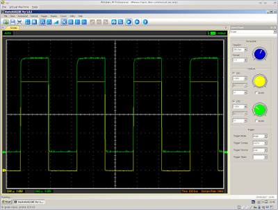
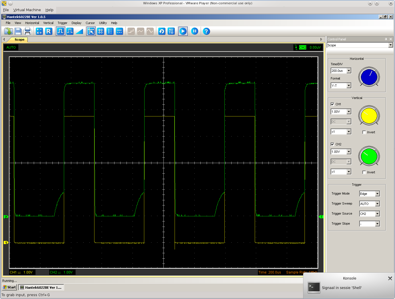
The oscilloscope view for
both situations (green measured on POT line, yellow on pulse line
before any components):

Full Arduino program
The following program
counts POTX and POTY from 0 to 255 in a loop. Arduino pin2 can be
used to pause the process: Put a wire between pin 2 and ground and
the counting stops. You can watch the program do its work by reading
registers $D419 and $D41A on the Commodore 64.
/**************************************************************************************************
Commodore 1351 mouse simulation code for Arduino
Written by Daniël Mantione
**************************************************************************************************/
volatile unsigned long sid_measurement_cycles=0;
u8 posx=0;
u8 posy=0;
bool commodore_is_pal = true;
ISR(ANALOG_COMP_vect) {
/* The SID has started its discharge cycle. We now need to synchronize the PWM, but first we do a
PAL/NTSC check.
This is highly time critical code: Any modifications here before the timer is set to 0 will
require adjustment of the PWM offset in set_potx/set_poty. */
/* This is untested on NTSC! A PAL system runs at less than 1MHz and therefore 512 SID cycles
will take longer than our 1024 timer cycles. Therfore we expect a low timer counter value when
the interrupt occurs. An NTSC system runs at higher than 1MHz and therefore 512 SID cycles
will take shorter than our 1024 timer cycles. Therefore we expect a high timer value when the
interrupt occurs. */
commodore_is_pal = (TCNT1 < 512);
/* In order to synchronize the PWM with the SID we will reset the clock prescaler of the
microcontroller and reset timer 1 by writing 0 to its counter: */
GTCCR = _BV(PSRSYNC);
TCNT1 = 0;
/* Timer has been reset, so end of time critical code. */
sid_measurement_cycles++;
}
void setup_comparator() {
ACSR =
(0<<ACD) | // Analog Comparator: Enabled
(0<<ACBG) | // Analog Comparator Bandgap Select: AIN0 is applied to the positive input
(0<<ACO) | // Analog Comparator Output: Off
(1<<ACI) | // Analog Comparator Interrupt Flag: Clear Pending Interrupt
(1<<ACIE) | // Analog Comparator Interrupt: Enabled
(0<<ACIC) | // Analog Comparator Input Capture: Disabled
(1<<ACIS1) | (0<ACIS0); // Analog Comparator Interrupt Mode: Comparator Interrupt on Falling
// Output Edge
pinMode(6, INPUT); //Avoid interfering with comparator
pinMode(7, INPUT); //Avoid interfering with comparator
}
void setup_timer1() {
/* For generating the pulses for POTX/POTY we will use timer 1 of the Atmega328p. This is a 16-
bit timer, which allows for high precision.*/
TIMSK1 = 0;
GTCCR |= _BV(PSRSYNC);
/* We set the clock source to none, so the timer does not run while we adjust it. The WGM12 bit
is to already select the right timer mode, otherwise OCR1A/ORC1B cannot be set correctly (read
on). */
TCCR1B = _BV(WGM12);
/* Activate PWM on Arduino pin 9 and 10. The PWM pin is high when the counter is higher than
MATCH. Select Fast PWM mode 7. */
TCCR1A = _BV(COM1A1) | _BV(COM1A0) | _BV(COM1B0) | _BV(COM1B1) | _BV(WGM10) | _BV(WGM11);
TCNT1 = 0x000;
/* WGM12=1 to select Fast PWM mode 7. CS11 selects a clock source of clkio / 8, which results in
2MHz. A timer clock of 2MHz combined with a range of 0-1023 is acceptable for our purposes. By
selecting a clock the timer starts counting */
TCCR1B = _BV(WGM12) | _BV(CS11);
DDRB |= _BV(PORTB1) | _BV(PORTB2);
}
void setup() {
setup_comparator();
setup_timer1();
/* Arduino timer 0 is used by default to support timing functions like delay(). Its interrupt
handler may delay the analog comparator interrupt and thus cause noise. Therefore switch it
off. */
TCCR0B=0;
pinMode(LED_BUILTIN, OUTPUT);
digitalWrite(LED_BUILTIN, LOW);
set_potx(0);
set_poty(0);
Serial.begin(9600);
Serial.println("Start");
}
void set_potx(u8 potx) {
/* Our timer runs at 2000KHz while a PAL C64 runs at 985 KHz.
This means that we need approximately 2 timer cycles for 1 C64 cycle, so multiply
by 2 */
u16 d;
d = 0x1f2 + 2 * potx;
/* However, because the difference is not exactly 2, this means our pulses would be slightly too short.
Compensate. */
if (commodore_is_pal) {
if (potx>=24) d++;
if (potx>=48) d++;
if (potx>=87) d++;
if (potx>=121) d++;
if (potx>=156) d++;
if (potx>=187) d++;
if (potx>=223) d++;
if (potx>=251) d++;
} /* TODO NTSC */
OCR1A=d;
}
void set_poty(u8 poty) {
/* Our timer runs at 2000KHz while a PAL C64 runs at 985 KHz.
This means that we need approximately 2 timer cycles for 1 C64 cycle, so multiply
by 2 */
u16 d;
d = 0x1f2 + 2 * poty;
/* However, because the difference is not exactly 2, this means our pulses would be slightly too short.
Compensate. */
if (commodore_is_pal) {
if (poty>=24) d++;
if (poty>=48) d++;
if (poty>=87) d++;
if (poty>=121) d++;
if (poty>=156) d++;
if (poty>=187) d++;
if (poty>=223) d++;
if (poty>=251) d++;
} /* TODO NTSC */
OCR1B=d;
}
void loop() {
int s;
if (digitalRead(2)) {
posx ++;
set_potx(posx);
posy ++;
set_poty(posy);
}
Serial.println(posx);
s=sid_measurement_cycles>>8;
/* Because timer 0 is stopped, we cannot use the normal delay() routines, so we have to
delay a different way. */
while (s==sid_measurement_cycles>>8)
{};
}
/**************************************************************************************************
Commodore 1351 mouse simulation code for Arduino
Written by Daniël Mantione
**************************************************************************************************/
volatile unsigned long sid_measurement_cycles=0;
u8 posx=0;
u8 posy=0;
bool commodore_is_pal = true;
ISR(ANALOG_COMP_vect) {
/* The SID has started its discharge cycle. We now need to synchronize the PWM, but first we do a
PAL/NTSC check.
This is highly time critical code: Any modifications here before the timer is set to 0 will
require adjustment of the PWM offset in set_potx/set_poty. */
/* This is untested on NTSC! A PAL system runs at less than 1MHz and therefore 512 SID cycles
will take longer than our 1024 timer cycles. Therfore we expect a low timer counter value when
the interrupt occurs. An NTSC system runs at higher than 1MHz and therefore 512 SID cycles
will take shorter than our 1024 timer cycles. Therefore we expect a high timer value when the
interrupt occurs. */
commodore_is_pal = (TCNT1 < 512);
/* In order to synchronize the PWM with the SID we will reset the clock prescaler of the
microcontroller and reset timer 1 by writing 0 to its counter: */
GTCCR = _BV(PSRSYNC);
TCNT1 = 0;
/* Timer has been reset, so end of time critical code. */
sid_measurement_cycles++;
}
void setup_comparator() {
ACSR =
(0<<ACD) | // Analog Comparator: Enabled
(0<<ACBG) | // Analog Comparator Bandgap Select: AIN0 is applied to the positive input
(0<<ACO) | // Analog Comparator Output: Off
(1<<ACI) | // Analog Comparator Interrupt Flag: Clear Pending Interrupt
(1<<ACIE) | // Analog Comparator Interrupt: Enabled
(0<<ACIC) | // Analog Comparator Input Capture: Disabled
(1<<ACIS1) | (0<ACIS0); // Analog Comparator Interrupt Mode: Comparator Interrupt on Falling
// Output Edge
pinMode(6, INPUT); //Avoid interfering with comparator
pinMode(7, INPUT); //Avoid interfering with comparator
}
void setup_timer1() {
/* For generating the pulses for POTX/POTY we will use timer 1 of the Atmega328p. This is a 16-
bit timer, which allows for high precision.*/
TIMSK1 = 0;
GTCCR |= _BV(PSRSYNC);
/* We set the clock source to none, so the timer does not run while we adjust it. The WGM12 bit
is to already select the right timer mode, otherwise OCR1A/ORC1B cannot be set correctly (read
on). */
TCCR1B = _BV(WGM12);
/* Activate PWM on Arduino pin 9 and 10. The PWM pin is high when the counter is higher than
MATCH. Select Fast PWM mode 7. */
TCCR1A = _BV(COM1A1) | _BV(COM1A0) | _BV(COM1B0) | _BV(COM1B1) | _BV(WGM10) | _BV(WGM11);
TCNT1 = 0x000;
/* WGM12=1 to select Fast PWM mode 7. CS11 selects a clock source of clkio / 8, which results in
2MHz. A timer clock of 2MHz combined with a range of 0-1023 is acceptable for our purposes. By
selecting a clock the timer starts counting */
TCCR1B = _BV(WGM12) | _BV(CS11);
DDRB |= _BV(PORTB1) | _BV(PORTB2);
}
void setup() {
setup_comparator();
setup_timer1();
/* Arduino timer 0 is used by default to support timing functions like delay(). Its interrupt
handler may delay the analog comparator interrupt and thus cause noise. Therefore switch it
off. */
TCCR0B=0;
pinMode(LED_BUILTIN, OUTPUT);
digitalWrite(LED_BUILTIN, LOW);
set_potx(0);
set_poty(0);
Serial.begin(9600);
Serial.println("Start");
}
void set_potx(u8 potx) {
/* Our timer runs at 2000KHz while a PAL C64 runs at 985 KHz.
This means that we need approximately 2 timer cycles for 1 C64 cycle, so multiply
by 2 */
u16 d;
d = 0x1f2 + 2 * potx;
/* However, because the difference is not exactly 2, this means our pulses would be slightly too short.
Compensate. */
if (commodore_is_pal) {
if (potx>=24) d++;
if (potx>=48) d++;
if (potx>=87) d++;
if (potx>=121) d++;
if (potx>=156) d++;
if (potx>=187) d++;
if (potx>=223) d++;
if (potx>=251) d++;
} /* TODO NTSC */
OCR1A=d;
}
void set_poty(u8 poty) {
/* Our timer runs at 2000KHz while a PAL C64 runs at 985 KHz.
This means that we need approximately 2 timer cycles for 1 C64 cycle, so multiply
by 2 */
u16 d;
d = 0x1f2 + 2 * poty;
/* However, because the difference is not exactly 2, this means our pulses would be slightly too short.
Compensate. */
if (commodore_is_pal) {
if (poty>=24) d++;
if (poty>=48) d++;
if (poty>=87) d++;
if (poty>=121) d++;
if (poty>=156) d++;
if (poty>=187) d++;
if (poty>=223) d++;
if (poty>=251) d++;
} /* TODO NTSC */
OCR1B=d;
}
void loop() {
int s;
if (digitalRead(2)) {
posx ++;
set_potx(posx);
posy ++;
set_poty(posy);
}
Serial.println(posx);
s=sid_measurement_cycles>>8;
/* Because timer 0 is stopped, we cannot use the normal delay() routines, so we have to
delay a different way. */
while (s==sid_measurement_cycles>>8)
{};
}
The input voltage
There is one final thing
to worry about. The program above gives the exact right result when
the Arduino is powered from USB. When powered from the C64, the
values are off by 1. It turns out that the cause is the voltage: My
voltage meter measures 5.11V on the Arduino when powered from USB,
just 4.91V when powered from C64.
Therefore, in order to
generate really 100% perfect results, it is necessary to adjust for
this. I think this can be done by burning a little bit of the voltage
with a zener diode like this:

The Arduino outputs
voltages of approximately 5V. The zener diode burns any voltage
higher than 4.7V away into heat. The BAT43 has an official voltage
drop of max. 0.33V, but my measurements show about 0.2V drop. This
means that any supply voltage higher than about 4.9V is burned away,
probably good enough for our purposes. We should be able to charge
the SID capacitors fast enough with 4.7V and knowing it is exactly
4.7 should eliminate the uncertainty about the exact input voltage.
The next standard zener
value below 4.7V is 4.3V. Here I have more doubts that we are able to
charge fast and high enough, but if so, this allows even more
tolerance in the input voltage and more choice in diodes.
I think will be a good
idea to design the Megastick PCB with room for both a zener diode and
potmeter: It is always possible to remove the zener later and replace
the potmeter with a fixed resistor, but at least initially it will be
very useful to do some manual adjustments in order to get exactly the
right value. 0-500 Ω is
probably better for accuracy purposes than the 0-1000
Ω that I used.
I was thinking about using
a MOSFET as an alternative, so you can avoid the diode and its
voltage drop:
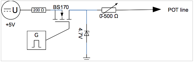
... but this probably
doesn't work: While the POT line is charged, the voltage between gate
and drain drops, causing the the MOSFET to turn itself off, likely
too early.
Saturday, 9 September 2017
That recent C65 sale on ebay
Just a quick post while I am in Vanuatu for work.
Many of you have probably already seen the recent ebay sale of a Commodore 65.
What is interesting here is that this unit is incomplete, lacking the video chip, without which it doesn't work, and yet it still sold for US$18K !
Meanwhile, we continue to chug away in the background on the MEGA65, which we can assure you will be cheaper to buy than that :)
Once this current spate of trips to Vanuatu and beyond for work settle down, I hope to make some more progress on keyboard and case moulding solutions.
Many of you have probably already seen the recent ebay sale of a Commodore 65.
What is interesting here is that this unit is incomplete, lacking the video chip, without which it doesn't work, and yet it still sold for US$18K !
Meanwhile, we continue to chug away in the background on the MEGA65, which we can assure you will be cheaper to buy than that :)
Once this current spate of trips to Vanuatu and beyond for work settle down, I hope to make some more progress on keyboard and case moulding solutions.
Subscribe to:
Posts (Atom)