Friday, 30 June 2023

MEGA65R4 Bring-Up

Well, we have the first samples of the R4 of the MEGA65 PCB:


This will be the model of PCB that finds its way into the next batch, plus or minus any last-minute changes that might have to be made.

The R4 includes a number of nice improvements over the R3A that was used in the previous batch, including:

1. Digital video back-power protection through the addition of a digital video driver IC.

2. Removal of the Intel MAX10 2nd FPGA to simplify the design. This means that the Arrow-compatible JTAG programmer would also not be required with the R4 board, since it was only ever required for updating the MAX10 FPGA.

3. Improvement of the 3.5mm audio jack quality with the addition of a nicer DAC setup.

4. Addition of a 64MiB SDRAM, that will mean that more MiSTer cores can be ported to the MEGA65.

5. Joystick ports will be bi-directional, allowing use of the Protopad and similar devices.

6. RTC chip has been replaced by another that should give us none of the problems of the previous one.

7. The RTC now takes a CR2032 battery and has a super-cap for battery-less time-keeping, at least for a while at a time.

As with all changes to boards, we have to test all the changes and get things working. As the R4 has a lot of changes, there are a lot of FPGA pins that have been reassigned, so the first job was to go through and update the XDC file to reflect this.

With that done, VGA output, SD card, keyboard input were all quickly confirmed working, allowing the MEGA65 R4 board to work in a minimalistic manner.  

The digital video output requires a slight tweak, as we attempted to build the boards without some allegedly optional pull-up resistors. However, due to the exact design we used, we do in fact need those resistors. Those are getting retro-fitted onto my R4 sample board in the near future.  In the meantime, I will keep working on other parts of the board.

Next stop is the RTC: The IC is completely different to the previous one, so I need to change the I2C address in the code, add address decode logic for the R4 I2C peripherals generally, and then remap the RTC registers between the two ICs, so that it is backwards compatible.  Otherwise the Configure program, BASIC65 ROMs, and anything else that uses the RTC would need patching.

The register map of the two ICs are:

For the new one, the important registers are:

for the old one, it was:


What we care about for backwards compatibility is that the current time and date registers match up.  Everything else can remain different, as only very specialised software will need to touch those. For those registers we find:

Register 0 = Seconds = Register 1 on the new one
Register 1 = Minutes = Register 2 on the new one
Register 2 = Hours (with bit 7 indicating if 24 hour time) = Register 3 on the new one (which has no 24 hour time flag, as it is always in 24 hour clock mode)
Register 3 = Day of month = Register 5 on the new one
Register 4 = Month = Register 6 on the new one
Register 5 = Year-2000 = Register 7 on the new one
Register 6 = Day of Week = Register 4 on the new one

The Grove external RTC support already has a mechanism for the rearrangement of RTC registers, so it should be possible to re-use that.

The new RTC also offers a 100ths of a second register in register 0, which it would be good to expose.

I have the RTC working reasonably now, so will turn my attention to the 64MiB SDRAM next.  To avoid long synthesis runs between each little fix, I want to use unit tests to test the SDRAM controller.  Ideally I would have a good VHDL model of the SDRAM itself, which I don't.  But I can probably make one that will be good enough.  

I'd also like to have a program that can take a VHDL file and auto-generate a VUnit VHDL test case template from that, to avoid having to do all the annoying boiler plate VHDL generation.  I've written these before, but not that's available open-source, so I'll do it from scratch again.  As an experiment, I'm going to use ChatGPT 4 to help write the tokeniser, as I always find that part boring and error-prone.  Using ChatGPT probably was faster, but was just as error prone, although the process was probably less boring!  

With the tokeniser, I can search VHDL source files for the entity definitions, and generate the lists of parameters required to instantiate the entity in the test case, and from that, auto-generate the boiler-plate for the entity (or entities) that I want to include in the VUnit test case, and then generate the VUnit test case boiler plate containing all that.  This will come in handy later for making unit tests that cover other parts of the MEGA65's VHDL.

I could probably just ask ChatGPT to generate a VUnit test case for a given entity, directly.  Maybe that's the easier approach here. I've used my 25 questions to ChatGPT 4 for the next 3 hours, so I tried doing it with ChatGPT 3.5, which was a fairly unmitigated disaster for making a complete test, however, it did a fine job when I pasted in two entity definitions for the SDRAM and SDRAM controller and asked it to instantiate them and connect them up appropriately. Well, by that I mean it compiles. It may well have connected them in a completely useless or insane manner.

At first glance, it might have done ok. We'll see. Actually, no. So now I am trying to use it to help me write a VHDL model for the SDRAM.  This is also producing VHDL code that kind of looks like it should be an SDRAM, but not quite. But it probably is still saving me some overall typing.

Well, that was an interesting experiment. In any case, I have now worked things to the point where I have the first unit tests with VUnit working, that check if the SDRAM initialisation sequence is given and received correctly using my model of the SDRAM and my SDRAM controller.  Now I am working on some tests for simple memory accesses. Once those are working, I can look at synthesising a fresh bitstream with it enabled, and see if the SDRAM talks to it.

Ok, bitstream has synthesised, but no sign of life when reading the SDRAM.  I'll go back to the simulation unit testing, and have a look at the waveforms generated when doing the reads and writes, and make sure that they look correct, in case I implemented the SDRAM model wrongly in a way that I haven't noticed yet.

Meanwhile, I am checking a couple of other things on the board:

First, I have confirmed Ethernet is still working, so that's one more sub-system ticked off.

Second, I want to get the bi-directional joystick behaviour working.  This should allow the use of the ProtoPad and similar fancy joysticks that have lots of buttons.  The MEGA65 R4 has some open-collector inverters that can be used to pull the lines low from the MEGA65 side when required. I have these setup to be activated when the DDR for a joystick line is set to output, and the value being written to $DD00 or $DD01 is a zero -- i.e., matching the CIA behaviour for output.  The read-side remains the same, as it does on the CIA, because its just the case of an output driver pulling the line low, which the input port of the CIA (on the same pin) correctly sees as a dropped voltage.

I seem to now have the joystick ports working for output as well as input, although some more extensive testing will be required to make sure I have the bits correctly ordered.

The next big annoying problem while I wait to get the pull-up resistors on the R4 board for the digital video output, is that BASIC 65 doesn't get to READY, as it seems to get stuck trying to read from the IEC bus.  It gets stuck in a loop checking for bit 6 of $DD00 to go high (the CLK pin), from what I can tell.  I've just double-checked the XDC file, to make sure I haven't messed up any of the IEC pin assignments on the FPGA, and they all look fine.  Time to look more closely at the plumbing for the IEC CLK line.

For each of the main IEC pins, we have 3 FPGA pins: One that reads the current voltage on the pin, one that enables the output driver, and one that sets the signal that is fed to the output driver.  This is technically a bit of an overkill, as it allows us to drive high, instead of just drive low, or go tri-state for reading.  Anyway, it means that for the signal on an IEC pin to be low, both the output driver has to be enabled, and the input to the output driver set to select a low voltage.

Now, looking at the R3 vs R4 schematics, the circuit for this has changed a little. It is now:

U20 takes the input from the IEC CLK pin (as SER_CLK) which is a 5V signal, and level-converts it to a 3.3V signal, F_SER_CLK_I.  The Output Enable (OE) signal that controls whether the F_SER_CLK_I pin is valid is active high, so that all looks fine. i.e., it seems like we should be ok there.  We also have a 4.7K pull-up to 5V, so it shouldn't read 0V if U15A at the bottom is not driving it low.  If F_SER_CLK_EN=0, F_SER_CLK_O=1, then we would expect SER_CLK to be driven low.  To allow it to float, F_SER_CLK_EN=1 should do the trick, since there is an inverter on the input of this line to U15A.  So why are we seeing the CLK line at 0V when I probe the physical port? 

Probably the best thing to do here is to make sure that the line can go high.  Resetting the MEGA65 does cause it to go high for a time, so things are ok at least partially. Ah, I think I see the problem. On the R3 board, this is the output logic for this line:


Note that the F_SER_CLK_EN line is using a non-inverted output enable line.  So I should just be able to invert the logic for F_SER_CLK_EN, and its equivalent for the other IEC lines, and it should fix the problem -- which it did.

Now to work on the improved 3.5mm analog audio output.  This is handled on the R4 by a AK4432VT DAC chip instead of a simple 1-bit digital output plus filter on the R3. This DAC chip uses I2S audio signalling, the same as the DAC used on the MEGAphone prototypes, so I'm hoping I can re-use most of what we have already made for that.

Working my way through the datasheet, and how we have it hooked up on the board:

1. Configuration mode is strapped to serial, rather than parallel (not yet sure what that means).

2. We want a sample rate <= 48KHz, so DFS0 and DFS1 must be zero, which is the default.

3. BICK frequency should be 2.8224 for 44.1KHz or 3.072MHz for 48KHz sample rate. 

4. MCLK freuency should be 11.2896MHz for 44.1KHz or 12.2880MHz for 48KHz sample rate.

5. For 512fs configuration, the 512fs clock should be 22.5792MHz for 44.1KHz or 24.576MHz for 48KHz sample rate.  256fs is not available at these sample rates, but it is for 88.2KHz and 96KHz sample rates.  Maybe we can use those sample rates instead off 44.1KHz or 48KHz?

6. Audio data is signed, MSB first, latched on rising edge of BICK.

7. There is an I2C interface that can be used to set left and right gain between +12dB and -infinity dB (= mute). $00 = loudest, $FF = mute. This interface has a "soft transition" feature, so gain changes shouldn't produces pops or clicks.

8. There is a hardware mute pin available, which has similar effect. This is connected on the MEGA65 R4 board, so we better not activate it by mistake! This line is active high, so we need to drive it low normally.

9. The power down line (connected to audio_powerdown_n) holds the DAC in reset while low.  Datasheet says that it should be bought low once and then released to ensure correct operation. It has to be held low for at least 800ns.

10. To avoid click on power up in (9), the mute pin can be applied before releasing the powerdown pin. That's probably worth doing.

11. To enable the I2C interface, $DEADDA7A has to be written as four separate transactions with /CS being released between each (see page 33 of the datasheet). We'll have to do that, as the DAC is strapped for serial configuration.

12. The software mute pin is also the /CS line for the I2C interface.

13. I2C interface is 400KHz normal speed I2C is probably best, based on conflicting information about 7MHz or 1Mhz or 400KHz modes.

14. There are 6 I2C registers ($00 -- $05), but the register field is 16 bits long. Thus each write transaction consists of at least 32 bits, plus the usual ACKs between bytes that I2C uses. All 8 registers can be written as one sequential transaction.

15. The six registers are listed on page 38 of the datasheet. From those we can see certain default settings:

  15.1 DFS0/1 = 0, selecting either 44.1KHz or 48KHz, as previously described.

  15.2 ACKS (automatic clock recovery) is disabled.

  15.3 DIF2-0 = 110, selecting 32-bit MSB aligned format. This means "Mode 6" timing, which is described in figure 15 on page 23 of the datasheet. This basically means that BICK needs to be 64x the sample rate, to allow for 2x32bit (left and right) samples per sample period.  For 44.1KHz, this means 44.1KHz x 64 = 2.8224MHz, and for 48KHz it is 48KHz x 64 = 3.072MHz. This matches (3) above, which explains how those are calculated.

  15.4 TDM1-0 = 00, selecting stereo mode

  15.5 SDS1-0 = 00, selecting normal L1, R1 channels.

  15.6 SYNCE = 1, enabling clock synchronistion

  15.7 SMUTE is disabled, allowing audio to be produced

  15.8 ATS, DASD, DASL (various filter related things) have sensible default values.

  15.9 ATTL/ATTR = volume levels for left and right default to $18 = 0dB, which is sensible.

And that's all the registers: So if we don't want to adjust the default volume level, we can actually ignore the I2C configuration interface completely, it would seem... which after synthesising the design up with all the necessary plumbing in place is indeed the case: We can completely ignore the I2C configuration.

I must say, the audio quality of this DAC is _way_ better than the old method. It sounds really nice and crisp and clear to my wooden ears at least. Listening to MOD files on the MEGA65 now sounds really nice  -- not that it was bad before. Enough so that I'm currently uploading a pile of MOD files onto my MEGA65's SD card to listen to, while I debug the remaining stuff. We really need one of the MEGA65 MOD players to support play-lists soon...

I've also spent some time debugging the bi-directional joystick functionality, and that's mostly working, although some strange thing has come up that is stopping Solitaire for the MEGA65 from being able to read mouse clicks, which are just the same as fire button presses on a joystick.  This will require some investigation to figure out the root cause. I have the source for Solitaire on the MEGA65, as I wrote the 1351 mouse driver for it, so I might have a poke and a fiddle into this.

Ok, so the problem in Solitaire is actually the high speed of the MEGA65's CPU vs the response time of 5V circuits: It just takes a few clock cycles at 40MHz before the DDR change to input allows the joystick inputs to float back high. In the case of Solitaire, just one extra clock cycle was required. I might be able to claw that back by making the DDR effects asynchronous, rather than waiting for the next clock-cycle edge.  Apart from that, the issue is considered closed.

So now we are back to figuring out what I have wrong in the SDRAM controller.  I have just added some debug registers to the SDRAM controller, so that we can confirm that data from the controller is making its way through the MEGA65 to the expansion device controller, and from there, into the CPU. If not, then that needs to be fixed, before I can tell whether the SDRAM controller is actually working or not.  It seems to be at least partly working, because it is issuing data strobes to the expansion controller, which I can tell because if this weren't the case, as it was before I plumbed it all together, the expansion device controller would timeout waiting from a response, freezing the CPU for millions of cycles before giving up.

And nothing is visible. Looking into the expansion device controller, it looks like it requires the presentation of whole cache lines from the expansion RAM. Nope, it can be configured to need that, but wasn't. So time to find where the plumbing is broken. We'll start by disconnecting the read data from the SDRAM controller, and feeding in a fixed value to the rdata signal, to see if that gets read or not.  That will tell us whether the problem is up-stream or down-stream of the SDRAM controller.

Ok, so when I export a constant value, instead of real memory accesses, it is visible.

So now let's see if we pretend to read a constant value from the RAM, that that is also visible. This will check if the RAM value export logic is working right, in particular, if the timing hand-over from the 162MHz to 81MHz clock domains is wonky or not. Well, in the process of doing that, I found two important things: 1. I hadn't actually connected the clock to the SDRAM in the R4 target. That will certainly not help ;) and 2. the rdata lines from the SDRAM controller were being set tri-state outside of a process, quite possibly overriding where they were being set within the controller process.  Both of those have now been fixed, and I'm synthesising the bitstream to test them.

Okay, so fixing those has my debug registers exported from the SDRAM controller visible, but accessing the SDRAM itself is still not working. But I can at least see if the controller thinks it is scheduling reads and writes via those debug registers now.

First up, I can see that the processor reads whatever was last read from the SDRAM controller, rather than the actually requested byte. This means that the data shows up "one read late".  For example, the SDRAM registers have the word "SDRAM" = 53 44 52 41 4D at $C000000. But when I read it, we get:

:0C000000:42534452414D00054242424242424242

i.e., one of those 42s from the end is read at the start (because I read this address block before), and our values are present, but not in the correct place. I'll have to figure out the cause of this, as it clearly won't be helping. That said, it shouldn't stop us being able to see written values being read back.

What we can also see in the above, is the "0005" part:

:0C000000:42534452414D00054242424242424242 

This is 2 debug registers that count the lower 8-bits of the number of reads and writes. It is showing $00 reads and $05 writes, because I tried to write 01 02 03 04 05 at $8000000 earlier.

So let's now read 16 bytes (=$10 bytes), and see what happens:

.m8000000
:08000000:42000000000000000000000000000000

.mc000000
:0C000000:53534452414D10054242424242424242

Two things to notice here: First, we see the $42 from the end of the register read showing up in the first position again. Second, we can see that the number of reads has jumped to $10, indicating that the SDRAM controller did see all the read requests.

So, given that this "out by one" read problem might be enough to cause real reads from the SDRAM to be missed, depending how the buffering works, I should work to fix that.

Looking at how the old HyperRAM controller works, that holds the data strobe line for an extra cycle.  I don't really see how that would impact things in terms of reading the old value.  It feels more like the data ready strobe needs to be delayed by one cycle, so that the value can be assured to be available when required. I'll try adding that delay, and see how it goes.

Well, that's resulted in some progress.  It is now clear that some bytes are being written to and correctly read back from the SDRAM. However, now the debug registers in the SDRAM controller can't be read.  Also, the addresses being written and read aren't lining up, and only even numbered bytes are being read back correctly -- but whether this is because odd numbered bytes aren't being written or aren't being correctly read I can't yet tell. But at least I have signs of life from the SDRAM!

I need to check that I haven't accidentally got cross-domain clock relaxation between the SDRAM and expansion controller, as an effect of clock names having changed, as that would screw things up real bad. It's quite tricky to tell what is being done in this regard in the Vivado logs, as the clock names are not trivial to map.  Anyway, I've removed them all except for the Ethernet to CPU clock and 12.228MHz (audio sample clock) to CPU clock domains, as those should be the only required ones. If synthesis takes forever, I can look at what the remaining clocks are that need relaxation between them.

So, the good news is that removing all those other clock relaxations didn't result in longer synthesis time, or a broken bitstream.  Unfortunately, it still hasn't got the $C000000 registers readable -- those are still timing out. Which is odd, because that part of the logic shouldn't have changed.  I have made a simulation unit test case for that, so let's see if it has now failing -- which it is. So let's see what's happened there.

Well, quite how it was working before is a bit of a mystery, because I found a really silly bug in the $C000000 register access code.  The test now passes, so I'm resynthesising...

While that is running, I'm thinking about the other bugs I have seen in the SDRAM controller: Primarily that the bytes are read out one word later in memory from where they should be, and that writing odd numbered bytes seems to fail, or at best, write zeroes.

For the odd-bytes-are-written-as-zero bug, I am seeing some interesting things:

s8000007 87

.m8000000
:08000000:87008000820084008700F07010204080

.s8000008 88

.m8000000
:08000000:88008000820084008800887010204080

.s8000009 89

.m8000000
:08000000:89008000820084008900880010204080

This sequence is giving me some more clues as to what might be going on. To see it more clearly, I wrote this little test program:

It clears out the first 16 bytes of SDRAM, and then writes values in progressively, to see what we read back after each:


We see again that the odd bytes are not written at all, and that the even bytes are pushed two to the right, and the first byte of each 8-byte block is whatever was written last.

So what I think is happening here, is that my SDRAM controller is using one too few cycles of latency when reading, thus reading (semi-)rubbish on the first word (remember the SDRAM has 16 bit wide bus).  Then separately, the write mask for the upper byte is messed up, or the data being presented in the upper byte is being written as zeroes instead of the correct data -- one or the other.

The odd-byte-write bug I can see clearly: We assume 16-bit wide writes from the expansion controller, instead of checking if its an odd-address 8-bit write.  I've now made a fix for that, which I will test, and then synthesise.

While possible fixes for that are synthesising, I think I'll work on the failing back-to-back write test of my SDRAM controller, and then on the simple cached reading.  Without any caching, reading from SDRAM to chip RAM is around 4.5MiB/sec, implying it is taking 9 clock cycles to perform a random read from the SDRAM. That sounds fairly plausible.

Ok, synthesis run has finished, and now all SDRAM reads are timing out. BUT it looks like the reads and writes are happening, more or less, and are visible in the correct addresses. So that's some positive progress. Upper 2 bits of data seem to be getting chopped, though. Let's see what happens in simulation with my unit tests, to see if we can't find and fix the problem there.

The bit trimming doesn't happen in simulation, so far as I can tell. After the latest bitstream synthesis my cache line stuff turns out to be working nicely, but the reads are still timing out. But with the cache, this now means reads happen in blocks of 8 (the size of one cache line) before freezing for a while until timeout occurs.

I think that might be caused by the data ready strobe being only 1x 162MHz cycle long, but it has to be caught by the 81MHz clocked expansion device bus. So I've now stretched it to last 2 cycles long, and will see if that helps. Meanwhile, I'm going to attack writing more tests for the SDRAM controller, including the cache I implemented, to make sure that it is not doing anything else detectably stupid.

Thanks to a pile of help from Adam, one of the great folks behind the C64 and other cores for the MEGA65, I have managed to get the SDRAM basically working now.  A lot of it was tackling the fairly tricky timing to get the SDRAM working at 162MHz with the FPGA.  There are some remaining timing closure issues, but it is already working stably. That is, once I remembered to implement refresh of the SDRAM! 

The remaining problems now are all related to the slow devices module that interfaces the CPU to the expansion RAM. Basically, reading sometimes returns stale data, rather than fetching the correctly written data. Reading from a different 8-byte region of the SDRAM fixes this problem.  The issue isn't the SDRAM bugging out reading the 8-byte blocks, but rather seems to be the CPU and slow devices modules messing up somewhere.  

To debug this I am adding a pile of debug registers to the CPU to see when it is reading from the SDRAM, and when it is using the new direct cache line read mode I have implemented, that should make linear reads from the SDRAM much faster -- but for unknown reasons causes a speed _drop_ of some 500x.  So something is clearly going wrong with the signalling there.  But the other problems still occur, even when that feature is disabled, so whatever that problem is, it is presumably separate from whatever is causing the reading of incorrect stale data.

A bit of poking about shows that the following kind of sequence can occur:

First, we can read an address, and see a value in it:

m8000808
:08000808:18191A1B1C1D1E1F0000000000000000

Then we write a different value into a different address, that is the same modulo 8: 

.s8000800 22

We can now read that address, and see that it is updated:


.m8000800
:08000800:221112131415161718191A1B1C1D1E1F

So far, so good.  Note that $8000808 contains $18 (underlined above).

Now the weirdness comes, if we try to read from $8000808 directly:


.m8000808
:08000808:22191A1B1C1D1E1F0000000000000000

Note that we end up reading the most recently written value, rather than the correct value.

If we now ask for it again from the modified address, we read it correctly:


.m8000800
:08000800:221112131415161718191A1B1C1D1E1F

But asking again for $8000808 reads back the most recently written value again:


.m8000808
:08000808:22191A1B1C1D1E1F0000000000000000

And I think I finally found the cause:  When making any access to the expansion RAM, the last written address is updated, instead of only when a write is occurring.

I'm fixing this now, and am confident that it should be fixed (and also fix similar problems with the HyperRAM on the R3/R3A boards). And following synthesis, I can confirm that this is the case: All cache consistency issues are now fixed. This has resulted in the apparent speed of copying from slow to chip RAM dropping, because it was previously erroneously using a cached result when it shouldn't have been.  Its now more like 4.6MB/sec, or about 7MB/sec if the single pre-fetch mode is enabled -- but that _does_ still result in cache consistency errors.

So that just leaves the problem of the SDRAM going hundreds of times slower when enabling the cache line reading directly by the CPU.  This is totally weird, as it can only save time for the CPU, not cost more time.

I can only guess that the CPU is getting confused thinking that it has to wait for the slow device ready toggle to flip before it can proceed. So I have made sure that when reading from the cache line, that the accessing_slowram signal is cleared.  However, if that fixes it, then it is revealing that there is some other deeper problem, where wait_states_non_zero is being asserted, even though I clear it in the case of reading via the cache line. In fact, I copied the perfectly working code from the case where we read the single pre-fetched byte from the slow devices unit, which effectively is just an indirect way of doing the same thing (and thus has higher latency).

Well, a lot has happened since I wrote the above, including tracking down a fascinating bug that was caused by accidentally activating writes with prefetch during the prefetch after a write.  That caused the most fascinating problem with random corruption of an entire DRAM row.  This is interesting on a couple of fronts. 

First, it was quite an adventure and process of elimination to work out what was going on.  Because entire DRAM rows were being corrupted, I figured it had to be something to do with the DRAM row activation and/or precharging when closing a row. Initially, I thought it was not having enough latency cycles during row activation or precharging at the end. Then I was very happy, because my SDRAM model for my simulation tests helped to find the problem really quickly: I wasn't clearing the WRITE+PRECHARGE command during the latency cycles. My simulation model of the SDRAM is purposely quite paranoid, and aborts the simulation if it detects you are doing anything that might be invalid -- and it flagged the issue strait away.

Second, I had only just been reading about how DRAM can be used as a true random number generator. Their method is to purposely not allow enough latency when opening a row, and triggers modest numbers of errors in a row when used.  What I was doing was causing lots of errors, possibly more than they reported in the paper.  I just dropped one of the authors a line to let them know what I discovered, in case its of interest to them.

Anyway, with that fixed, that got it working.

The next step is to improve the performance by not closing the DRAM row after every access, so that we can avoid the row latency for linear reads.  This will also be kinder to the SDRAM, rather than basically implementing ROWHAMMER as the default mode of operation ;)  It would actually be interesting to see if it prone to ROWHAMMER. 

Okay, that didn't take too much effort to implement.  Now the only remaining bug is if the SDRAM read cache-line feature is enabled (which is disabled by default because of this), occasionally a read request doesn't respond, causing a timeout of 2^23 clock cycles. I've reduced that to 32 clock cycles, so that when this happens, it doesn't cause the machine to freeze for a fraction of a second. 

I've also made selection between HyperRAM and SDRAM on the R4 selectable at synthesis time. So let's compare the performance of the two. Note that the HyperRAM implementation benefits from the fixing of the pre-fetch bug, thus HyperRAM performance is also improved over what we have seen previously on the R3:

First, with the HyperRAM. Note that there is actually no Trapdoor Slow RAM in this machine, so it is showing some slightly random numbers for that:

 
And now with the SDRAM:
 

We can see that it is faster across all measures -- especially copying between regions of the expansion RAM is now more than twice as fast, because the latency of the SDRAM is quite a bit lower than of the HyperRAM.

If I ever get the SDRAM cache-line bug fixed, then the speed of copying from slow to chip RAM will approximately double again, to around 16MB/sec, only 20% slower than copying from chip RAM to chip RAM -- but I've run out of puff right now to work on that.  My goal was really just to get the MEGA65 R4 board working, and confirm it has no known problems vs the R3A board, which I have achieved. 

This means that Trenz Electronic can now move forward to the next steps (of which there are still a few to go) of having the next batch of MEGA65's produced, which will be based on this new R4 PCB -- which we are hoping will come out later in 2023, probably Q3.

Sunday, 12 March 2023

Hi-res V200 character mode

While fixing some other bugs in the MEGA65 today, I took the opportunity to implement an improved character mode for clearer text. The basic idea is that in V200 text mode, i.e., 25 rows of text mode, that each row of pixels is vertically duplicated, because the native video mode is still V400.  In this mode, we can instead interlace which of the two C64-style charset ROM areas we pull the pixel data from, and display them on alternate lines.  Note that this doesn't result in flashy interlace, because it is a per-raster line interlace, not a per-frame interlace.  

NOTE: This post describes an optional feature that has been added. The default behaviour remains the same, and the MEGA65 will keep on booting up looking like it always did.  This just creates a new option for programmers (and users) to make use of, to give their MEGA65 a different look.

The change itself was quite simple, just checking if we are on the repeated pixel row for a character, and if so, and its coming from the character ROM, then use the alternate character ROM's data, if this feature is turned on via bit 4 of $D07A.

Here are some examples of the end result:


And now a bit of description of how I got there...

The first step was to enable bit 4 of $D07A on the new development bitstream I built that has support for this feature:

You can see the upper and lower-case characters getting mashed together. Also, we still have CRT scanline emulation turned on, which we should really turn off for this mode:
 
 
Next step was to load a font in the appropriate format. I made a tool called fontmunge.c in the mega65-tools repository that takes a 4KB 256 character 8x16 bitmap font, in this case the standard VGA font, and rearranges it into the correct byte order to display all the characters correctly:


However, because the font is ASCII, and not C64 screen code order, the letters are all messed up. Also, we don't have reverse characters.

A bit more fiddling with fontmunge.c, and both of those issues are now resolved. I still don't do anything about the PETSCII graphics characters, as you can see in the shot below, but the text is there and looks really nice and crisp, after I turned off the CRT emulation!

Here's another example showing a directory listing, complete with reverse text in the header line:


Friday, 6 January 2023

Adding colour to the MEGA65's Composite Output

In the last episode, we got the composite video output of the MEGA65's expansion board working -- but only in monochrome.  Through trickery, we were getting more than 16 shades of grey out of our 4-bit DAC (and we have further Cunning Plans :tm: to extract even more, but that's likely to be described in another blog post).  But what we really want right now, is working colour. For both NTSC and PAL.

In this post, I manage to get PAL non-interlaced composite video working with pretty decent colour signalling, producing images like this:


First step, get those colour bursts in the raster lines where they need to go, and only in the raster lines where they should be, and with the correct phase.  The book Video Demystified continues to be my able assistant here, with lots of deep technical information. The book can be easily found and purchased via online search.

The colour burst pulse should be 9 +/- 1 cycle at the appropriate frequency. I setup the mechanics for generating that in the previous blog post, but didn't actually hook it up, so I'll do that now, and see if we can't get that sorted fairly quickly. Interestingly, according to this image, the C64 had a much longer colour burst, presumably because it can only help the receiving monitor to have more cycles to lock onto the phase of. It also displayed an invisible white pixel on the left edge, presumably to help monitors calibrate the luminance more stably.

raster15khz_skip is conveniently counting down the 108 pixel ticks from the start of the HSYNC pulse.  That covers a total of 12 usec, so we can just check for about the half-way point, and then add the colour burst signal.

We have to scale the colour burst down to a range of +/- 37 instead of +/- 127. I'm willing to bet that a simple divide by 4 to make it +/- 32 will work fine. We also need to synchronise the colour burst to start at $00 or $80 hexadegrees (see my previous post for a bit more discussion on the hexadegree system of 256 = $100 hexadegrees in a circle).

Okay, I have added logic to clamp the phase at the start of the colour burst, and then to selectively super-impose it onto the luma signal after the sync pulse. It looks something like this:


The wiggly lines are the colour burst. What is important, is that it starts from the centre line, rather than some random point on every raster line. This is right, so that's good.  I reckon I can start the burst earlier, and have more cycles, like the C64 does.  I can also slightly tweak the end time, so that it always ends on a zero-crossing, rather than having a glitch. Both of those are now done.

So in theory if we now modulate the colour components onto the colour burst signal, we should see colours.  And this is where it gets fun. We will focus on PAL first.  The luma signal is actually already a combination of the red, green and blue channels.  This is called Y. Then to get all three, we need to have U and V, which are other combinations of the red, green and blue.  This structure is based on the historical development of colour TV as an overlay onto the existing black and white TV signals, combined with some clever insight into the sensitivity of human vision to different colours.

What matters for us right now, is the equations for U and V. These should be gamma corrected first, but I'm going to leave that for now. It just means that the colour saturation curves will be a bit wrong. Gamma correction can be added in later, essentially just using a 256 entry look-up table that has the gamma corrected values, and which is pre-applied to the red, green and blue channels.

But back to those equations:

Y = 0.299R + 0.587G + 0.114B
U = – 0.147R – 0.289G + 0.436B = 0.492 (B – Y)
V = 0.615R – 0.515G – 0.100B = 0.877(R´ – Y)

Since Y is already transmitted as luma, which is mostly the green channel, with a bit of red and a bit of blue, the U and V signals are the differences between the red and blue channels and Y. Note that this means that U and/or V can be negative at any point in time.

The U and V signals are then modulated with the colour burst signal: U with the sine of the current colour burst phase, and V with the cosine of the colour burst phase. This means that they are encoded "90 degrees apart", using what is called "I/Q" or "quadrature" coding. There is a lot of clever-pants signal processing that can be done with I/Q signals to extract the I and the Q parts back out at the other end. Fortunately we don't have to separate them, but just combine them, which we just do with simple addition.

The literature indicates that the modulated U and V signals should then be "saturation limited", so that if the magnitude of the values are too great, that they get clipped, rather than wrapped. This makes sense, as it just limits the red and blue aspects of the signals.

We will need a bit of a pipeline to generate U and V, scale them, and then modulate and saturation limit them.  The Y signal will need to be similarly delayed so that the components all stay in phase.

Ok, I now have the colour signal super-imposed over the luma signal.  However, I think the amplitude is too large, so I'll try cutting it in half. This is what I am seeing:


The checkered pattern is the direct result of the over-amplitude chroma signal, as far as I can tell.  What is interesting, and I don't really know why it is happening, i how the parts of the display that are being displayed more or less correctly, seem to be getting dithered.  

Now, the quadrants of the image that are being displayed properly are those that have blue on full, and more red than green. Not yet sure what clues that gives me.  Let's look at the chroma amplitude first, anyway.

This is how it looks at the moment, when we look at the raw signal:

We can see that the amplitude is much greater than in the colour burst itself. That should be fairly easy to fix.

Also, the bandwidth of the chroma signal is also way too high, as evidenced by the very jagged nature of the signal.  This is a problem, because the chroma signal is only allowed to occupy ~1MHz of bandwidth.  I'll likely need some kind of low-pass filter to solve this problem. I'll have a think about that while I fix the amplitude.

That's looking a lot more sensible to me.  Let's hope it fixes it.  Even if the bandwidth is bad now, the vertical colour bars are wide enough that they show up as areas with constant phase, and thus very narrow bandwidth, and they really should show up in colour. So I'll synthesise that, while I think more about limiting the chroma bandwidth more generally.

One of the things that has confused me about the chroma signal for PAL and NTSC, is what the actual horizontal colour resolution really is. As the carrier is ~4MHz, it can't be higher than that.  In fact, it probably has to be somewhat less than that, probably of the order of 2MHz or so.  Compared to our ~13.5MHz clock, that's close to one character wide.  

In fact, if we remember back to the C65's composite output, that's probably close to right: Trying to display, for example, a red character on a blue background resulted in unreadable rubbish, because at the ~8MHz pixel clock of the C64, it couldn't change between red and blue every pixel, because the result would be above the colour carrier.  Whole characters could be alternately coloured, however, without much trouble. So it's probably about right. It will be interesting to see if we get that kind of problem with the corrected colour amplitude, or if the monitor still refuses to show it in colour.

Still no colour, but the stippled pattern is less pronounced. My best guess at the moment is that it is Chroma Dots caused by the colour signal not being decoded, because the TV is treating it as a monochrome signal still.

Ah, there is a good clue in here. Apparently you _don't_ reset the phase of the colour carrier every raster, but leave it running, exactly as elpuri describes "despite what all those nice diagrams always show". And that has certainly helped! The monitor now clearly thinks that it is dealing with a colour image, even if things are rather broken:

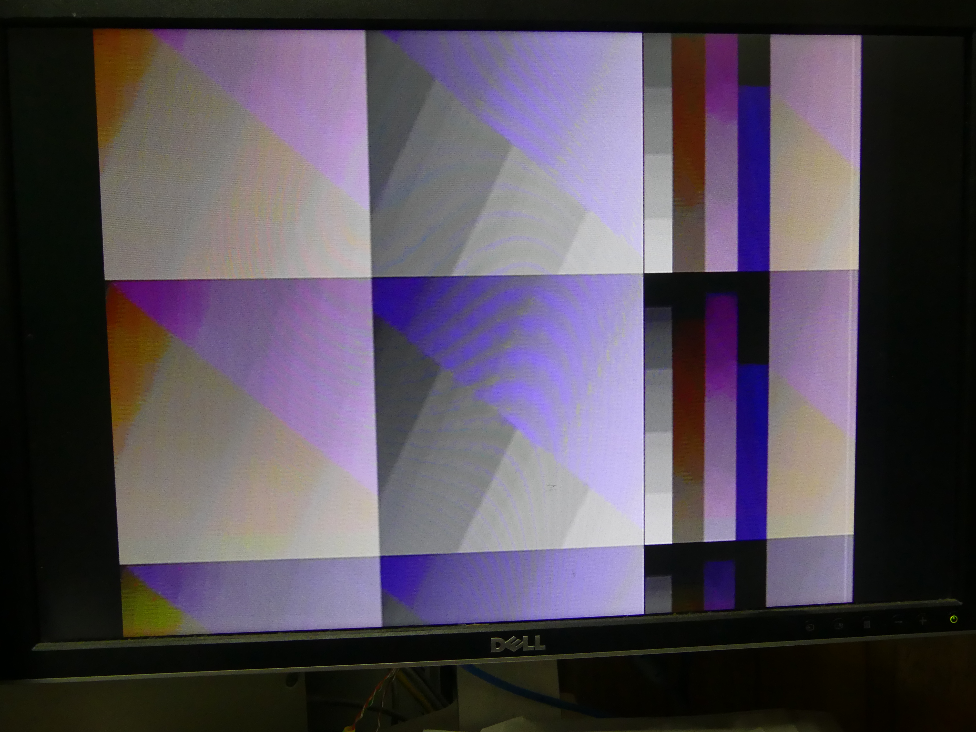
The first image is of the PAL display:

 
The colours are clearly pretty messed up.  NTSC is not quite as messed up, but it's all rather relative:

With NTSC it looks like I am encoding red as green.  The upper right triangles of the middle section are actually not far off the correct blue gradient that is expected here.

Thinking about it, this test pattern has really quite chroma low bandwidth requirements, because the colours largely transition gradually. So I should be able to get it working here, without having to fluff about with low-pass filtering the chroma signal. That can be dealt with later.

I'm tempted to remove one of the U or V channels temporarily to simplify the debugging.  It would also be great at this point to be able to access a "correct" composite display of the test pattern, so that I could compare it. I was hoping my VP-728 upscaler might have composite outputs, but it doesn't.

So I'll start by synthesising with just U, and no V component.  I might also just try outputing the RGB as YUV values directly, since that should generate a valid image, just with messed up colour space. If that still has non-coloured sections, then I will know that there is something else messed up.

Okay, so with either U or V disabled, I am indeed getting less colouring.

Hmmm.. I've reworked the sine table lookup stuff a couple of times, and I'm now more happy that that is doing what it should. PAL colours are still messed up, and missing from some areas, especially where red dominates the colour. NTSC colour encoding is still quite incomplete, as I am basically using PAL encoding in all modes right now. But it's progress.  

Now it's time to look at all those PAL phase changes, and check how I am going with that. I know that I am not inverting the phases each field, which is causing the colours to switch between two different rotations of the colour wheel.  So that's the first one to fix, I think.

The first thing to tackle is that the phase of the V component is supposed to alternate every other line. With that in place, it's "less bad", but not perfect, as I still haven't implemented the inter-frame correction.

There are also still large areas that are lacking colour. Investigating this, I have found that green coloured areas are resulting in rubbish colour information.  A single pure colour should generate a similarly pure sine wave with the correct phase that indicates its hue.  But instead, I'm seeing choppy rubbish like this:


The nice sine wave is the colour burst at the start of the raster line. Then the choppy stuff is all supposed to be pure green (RGB = #00FF00).  Pure red doesn't have this problem.

Now, one of the interesting things with the quadrature encoding method that PAL and NTSC use, is that a mixture of a pair of sine and cosine waves with the same frequency and kept in phase, will generate a signal of variable amplitude and phase, but at the same frequency.  Thus for a region with constant colour, regardless of the colour, we should see a nice continuous sine wave. Not this kind of choppy rubbish.

Disabling either U or V colour information resolves it -- not surprising since it will result in either a pure sine or pure cosine component from the remaining signal.

Ah! I found the problem: When combining the U and V signals after multiplying them by the sine and cosine table entries, it is possible for the result to overflow the variable I had defined. By adding an extra bit of precision, that problem has now gone away.  I'm not sure that the resulting amplitude is now high enough, but that is something fairly easy to fix later, if the colours are undersaturated (which is how that problem would manifest).

I'm synthesising a test bitstream for this now, and am quietly hopeful that it will fix a lot of the rubbish I was seeing, because a lot of it can be explained by pseudo-random patterns moving from the colour space to luma space -- which is exactly what would happen if it was saturating and then wrapping around instead of clipping.

And indeed that has helped: There are now colours that are still wrong, but there is no longer spotty rubbish caused by random looking colour subcarrier wave-forms. Here is how the PAL test pattern looks now:

Now I think the most fruitful thing to attack will be the correct handing of the phase inversion that is causing the colour to still flicker between two different hues all the time. This unfortunately can't be seen in the photo, because of the short shutter time. Figures 8.16a and 8.16b in Video Demystified has the information we need here, so I'll progressively implement it. 

I'll start with fake-progressive, as that has by far the simplest arrangement.

In the process I found I was setting the PAL colour burst frequency using degrees instead of hexadegrees, which mean that it was using funny angles: 135 hexadegrees = 190 degrees and 225 hexadegrees = 316 degrees, giving an angle between them of 126 degrees, instead of 90 degrees, and likely to be causing all sorts of problems.  Let's see if that improves things. Not noticeably, except that it removes the need for some fudge factors I had previously added, so that's a bonus. I also noticed I have -V on the wrong half of raster lines, so fixing that, too.

But now back to getting that sequence of suppressed colour bursts and phase inversions at the start of each field.

Hunting around the internet for tools to make the debugging of the video more efficient, I found cvbs-decode, which can decode raw PAL/NTSC video (but I can't get it to run, due to some weird python errors), and also the HackTV PAL/NTSC video generator for HackRF written in C.

The HackTV stuff is essentially an implementation of what I want to do, just in another programming language. Thus it could be a good place to mine for clues on what I am doing wrong.  The code is structured very abstractly, however, so that might take me a while.

Coming back around to the parts of the test pattern that lack any colour at all, I am looking at the waveforms I am producing for those, and I can actually see that there is in fact no colour subcarrier visible for that part of the image.  That's at least one thing that I can tackle with the tools I have already created, so I'll bash against that for a while.

The main area that is showing no colour is the triangle that has more red than green, and has blue at full value.  If there is more green than red, then it seems to be ok. Looking closer, there is a colour signal, but the amplitude is really low.  I had to reduce the colour amplitude by 2x while implementing it, to prevent over-flows. It's possible that I have over-attenuated it.

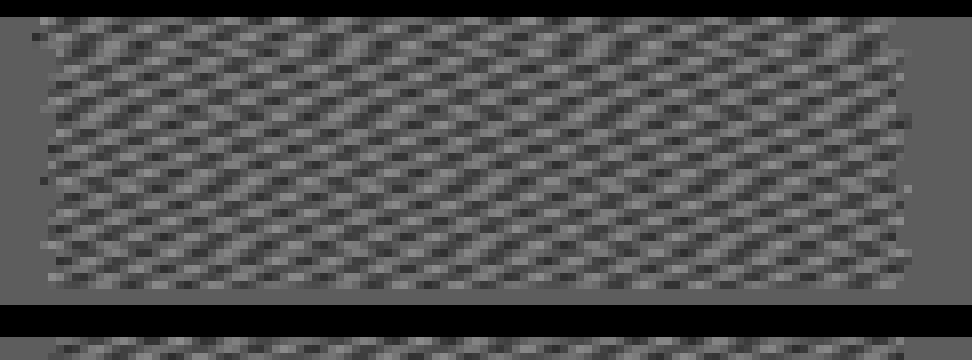
Meanwhile, to try to improve my workflow, I have improved my little trace program so that as well as a PDF with oscilloscope like traces, it now also produces an HSYNC-synchronised PNG view, effectively showing the whole video frame, including SYNC pulses (as black).  The PAL colour information will appear as dot/stripe patterns, as it would on a black-and-white TV.  After fixing a few bugs that it helped me to find, this is what I see for the PAL interlaced video:


You will probably need to click on the image to view full-size, as it has a fairly horrible aspect ratio.

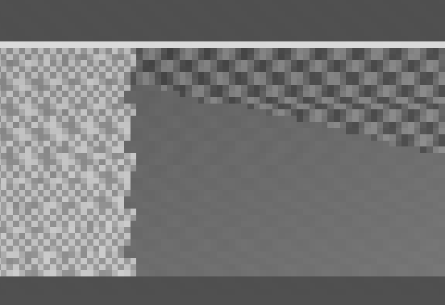
One thing about showing the colour information directly without decoding, it means we can by eye see the colour intensity by how bright the pattern is.  Here is a zoom-in of part of it:

Here we can see two regions with quite high colour saturation, and between them in the lower-right area, a section that still has some colour information, but the pattern is quite faint, meaning that the colour intensity is very low.  This is the area that should be purple. This clearly means that we have some problem with the YUV generation, and explains the lack of colour on the PAL monitor, because it really isn't there, or rather, is so faint, as to be effectively invisible.

One of the colours that is having this problem is #5800FF.  Let's do the YUV calculation by hand, and see how we think it should show up.

Let's apply the YUV calculation to this colour: 

Y = 0.212R´ + 0.700G´ + 0.086B´  = 0.0482 + 0 +  0.086 = 0.134
U = 0.492(B´ – Y) = 0.492 x 0.866 = 0.426
V = 0.877(R´ – Y) = 0.877 x (0.345 - 0.134) = 0.185

Scale these up to 8-bit range, and we get:

Y = 34 = $22
U = 109 = $6E
V = 47 = $2F

Hmm... The values I have in the VHDL are nothing like that. Y itself is quite different, for a start. Now, there are two ways to calculate U and V: The method above, or by applying direct RGB coefficients:

Y = 0.299R´ + 0.587G´ + 0.114B´
U = – 0.147R´ – 0.289G´ + 0.436B´ = 0.492 (B´ – Y)
V = 0.615R´ – 0.515G´ – 0.100B´ = 0.877(R´ – Y)

Hmm, these coefficients are different again for Y, that I got from a different part of the document.  They do seem to match what I am using in the VHDL, though, so let's start by checking those.

Y= 0.103 + 0 + 0.114 = 0.217
U = -0.051 - 0 + 0.436 = 0.385
V = 0.212 - 0 - 0.1 = 0.112

Scaled up, we get:
Y = 55 = $37
U = 98 = $62
V = 54 = $36

The VHDL is producing:

Y = $1D
U = $10
V = $04

In short, I have something very wrong going on with my YUV calculations in the VHDL, because the ratios between these values are not correct.  It's a little more complicated to debug here, because the VHDL doesn't do x256 scaling, because it reserves part of the 8-bit range of the DAC for SYNC and head-room for colour coding.  Thus I calculate Y with a different scaling factor compared with U and V. That said, U and V are calculated with the same scale factor, so the ratio between those two should hold. So lets look more closely at those:

U = – 0.147R´ – 0.289G´ + 0.436B´ = 0.492 (B´ – Y)
V = 0.615R´ – 0.515G´ – 0.100B´ = 0.877(R´ – Y)

For U, the VHDL does: U = -6 R - 12 G + 18 B. Those ratios look ok.

For V, the VHDL does: V = 18R - 15G - 3B. Again, those ratios look ok.

So where have I messed up?  Let me double-check the direct calculations:

U = – 0.147R´ – 0.289G´ + 0.436B´
U =  -0.147x88 - 0.289x0 + 0.436 x 255
U = -12.936 - 0 + 111
U = 98

So U looks ok. Now to V:

V = 0.615R´ – 0.515G´ – 0.100B´
V = 54 - 0 - 26 = 28

Ah, so I made an error in my calculations above (which I marked with the underline).

So in fact the ratio of U and V is about right.  

This makes me then suspect that the colour saturation is too low, i.e., that we need to scale up the chroma signal.  But it already has quite a bit of amplitude for some of the other colours.  So maybe I should implement the gamma correction first, instead.

PAL should use a gamma correction of 2.8.  There are plenty of online gamma curve calculators that can be used to generate a suitable table. Although the NTSC/PAL preferred curve is a little more complex:

For R, G, B < 0.018 

R´ = 4.5 R
G´ = 4.5 G
B´ = 4.5 B

For R, G, B ≥ 0.018

R´ = 1.099 R^0.45 – 0.099
G´ = 1.099 G^0.45 – 0.099
B´ = 1.099 B^0.45 – 0.099

Gamma is now implemented.  I'll synthesise a bitstream to see how it looks. But what I can already tell is that it hasn't fixed the lack of saturation of the purpley areas in the simulation.  So there is still other problem.  But it's nice to have at least one of issue eliminated.

Looking at the specifications for NTSC and PAL video again, I think I have the colour burst amplitude too high, which causes the monitor to interpret the colour saturation as being too low. Currently it has a peak to trough amplitude of 64 = $40 via 3 bit shifts of the sine table.  But it is supposed to only rise or fall by 1/2 of sync voltage.  With our scaling, that means it should be +/- $18, for a range of $30.  So it
will be contributing to the problem, but is probably not enough to be the root cause.  I'll fix it, anyway.

Meanwhile, looking at the images on the monitor instead of simulation again, the colour alternation flicker is annoying me a lot. So I am going to try a fix for that: I am suspecting that it is the phase alternation polarity should be switched every field -- although I cannot yet find clear information on this.

I've also introduced some sort of regression into the NTSC image, which I need to deal with.  Ah, found that. Also affects PAL when interlace is enabled. I was a bit over-zealeous in marking the active vs non active area, and was marking some of the active area as inactive, causing it to blank.

Resynthesising again... That's fixed the regression. 

I think my next step to track down the lack of chroma intensity when R > G, and B = full. I'll attack this by making a simple program in C that does the same YUV conversion, to see if I haven't just messed something up in the VHDL calculation.

Here is my hand-calculated Y, U and V panels for this pattern:

The V panel is showing much the same problem -- so this is good -- it means I have misunderstood something about the process of calculating these values. I'm guessing I'm not handling negative values properly.

U and V have ranges centred around zero, So this kind of sharp transition can appear.  By correcting this in the C program, I am able to get much saner looking panels:

Much better, with no nasty lines going through.  Also, it makes sense the way that U and V have peaks in particular corners, as U is basically the "missing blue" and V the "missing red".  As the pattern I am rendering here has increasing red as we go down the image, it makes sense that the missing blue component will decrease a bit (U, in the middle), while the missing red component (V, on the right) will increase.

So now to figure out what I have wrong in the VHDL when handling U and V.  The values I am generating are signed.  So I suspect that when they go negative, the multiplication is ending up flipped, and for some reason the sign bit is not being interpreted properly.

Okay, that seems to have helped: Now when I simulate the VHDL, I am seeing a much more even colour intensity.  That said, it is also quite faint, as you can see here below how the chroma oscillation pattern (the angled bars) have very low intensity:

In comparison, the colour burst that tells the monitor how bright they should be for maximum colour saturation is much more intense:

So I have one or the other not in the correct amplitude. 

The correct amplitude variation is +/- half of the sync level, i.e., +/- 24.

The colour burst part is indeed too intense.  The generation of this is a bit fiddly, because of how I do a pile of bit-shifts to avoid multiplications. But the luma_drive signal is generated as a 10 bit value, and the colour burst is added onto that.  This means we want an amplitude of +/- 24*4 = +/- 96, since the range is 10 bit instead of 8 bit. I think I have that right now.

As for the U and V signals, those I don't think are scaled the same, so will need to be fixed. 

Right, I think I have fixed the scaling of U and V, and the result looks much more promising now:


The intensity of the colour burst and of the chroma in the active area look reasonably well matched now.  I'll take a look at the oscilloscope view to be sure:

If anything now, I reckon the colour burst might be slightly lower amplitude than the pixel data.  But that should be fine.  Let's try making a test bitstream from that, and seeing how it looks:


Okay, that is stacks better. There are still problems, but we do at least now have fairly consistent colour saturation.  It's still flickering between different hues, especially in the left most panels, though, and of course the hues are not correct.  The four narrower bars are supposed to be grey, red, green and blue, which they clearly aren't. That said, the green and blue ones are kinda the right hue.  In fact, I would say that in general, it is red that has the most problems in the whole image.

Red in PAL comes mostly from the V signal, which is supposed to alternate phase every raster line.  Thus it seems quite plausible that there is something wrong with that logic.  

Ah, found a very likely cause: The colour burst signal is also required to swing by 90 degrees between normal and inverted V signal lines, as described here. I was adjusting the phase of the pixel data colour, rather than of the phase of the colour burst. This was likely causing the problems. Rearranging that now, so that it does it the right way, and hopefully we will see stable colour in PAL -- even if the red channel is still not quite right (there is a 50% chance I have it inverted).

Look like I got it the right way around:

It's not perfect, as red is still under-saturated compare with blue, which I can improve. Also green is a bit under-saturated now, too. But it is a million times better than before. It is recognisably a colour PAL display.  The non-linearity in the DACs is probably now as much of the problem as anything else, and might in particular be responsible for the uneven colour saturation in places.

But, let's see how a MEGA65 bitstream looks with it:


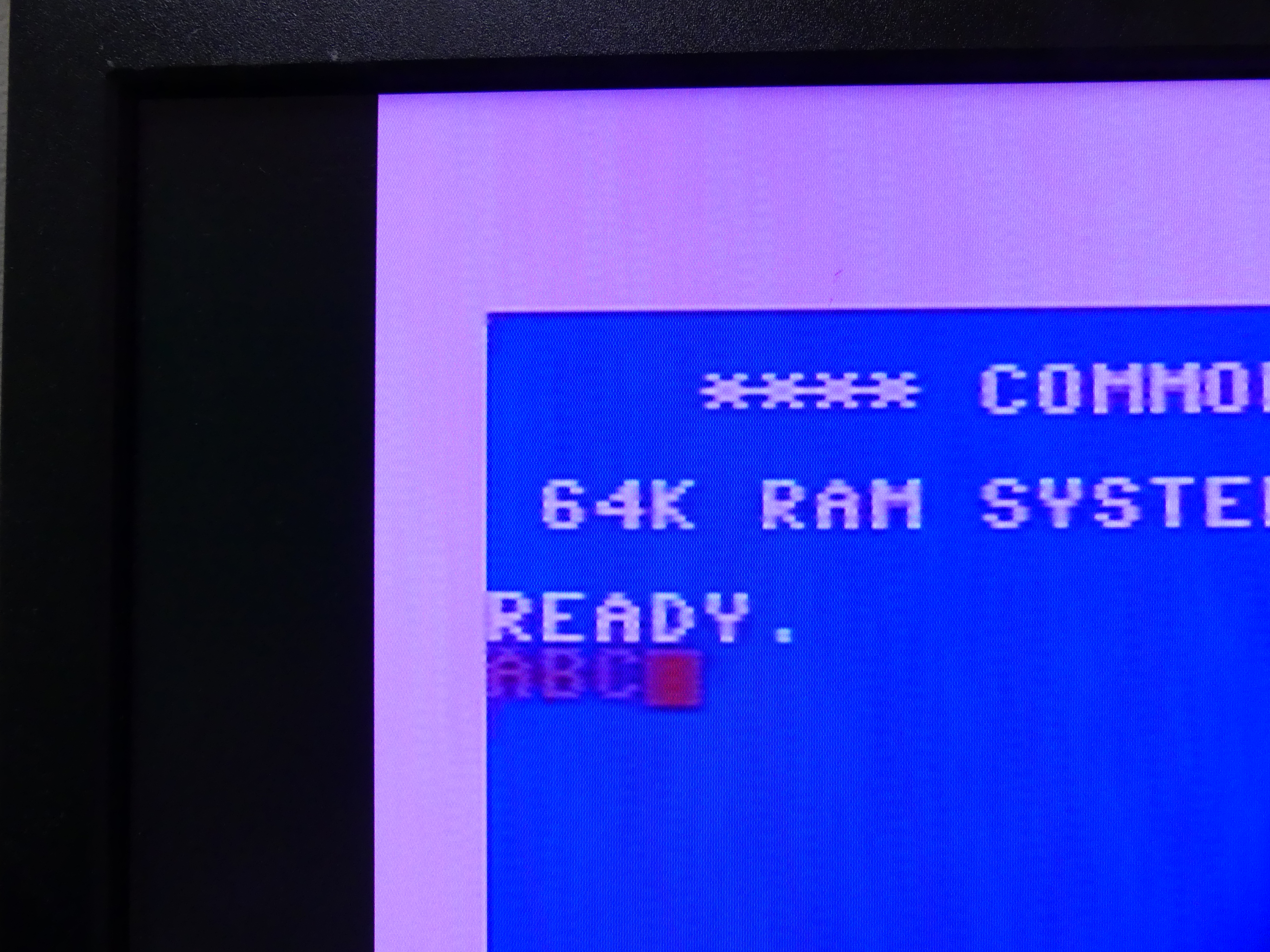
Not, bad, I have to say :) I wasn't sure that 80 columns with colour would still be readable.  That said, the camera has corrected what is a very real purple tint on the display.   My crappy phone camera does a fair job at reproducing the tint, though:

While I'm running things, let's see how C64 mode / 40 columns looks:

I have to say, that this looks pretty darn good, apart from the purple tint. It is absolutely clearer than using the composite output from a C64. In fact, you can even do red text on blue background, that normally disappears into soup on a real C64:


The good camera has again desaturated the red a bit. The text is actually much more coloured. Again, out with the crappy phone camera to see how it really looks:

Well, how it looks in terms of colour, because my phone camera has horrible focus. The other camera correctly captures the sharpness, though.

So that's all good. The only problem now is that the interlaced mode of PAL now has colour instability. This is odd, as it was previously the other way around. Ah, no, I only thought it was the other way around ;) It is indeed consistent. That makes it much easier to investigate and fix.  

But this blog post is now more than long enough, so I'm going to wrap it up here.

What I will say, though, is the VHDL part of this is now more or less all there, and with support, should be quite feasible for someone to contribute to, rather than myself continuing on it ahead of other competing priorities. So if you have an interest in composite video output (you don't need to know anything about how it works up-front), and would like to learn some VHDL and contribute to this feature on the MEGA65, drop in on the MEGA65 discord server (link from https://mega65.org).


Comparing the Graphics Capabilities of the MEGA65 and Amiga

This post is just a quick summary of some replies I gave on Facebook recently, when people were asking questions that made it clear that they had the mistaken belief that the MEGA65's graphic system is not powerful.  This is a repeating theme I have noticed around the internet from time to time. Perhaps it is because a lot of people do things on the MEGA65 that are not graphically taxing, like playing Infocom text adventures. Anyway, someone posted a question that was along the lines of: "The MEGA65's graphics seem pretty underwhelming", and with the Amiga being given as a point of comparison.  So I wrote the following explanation, that I figure will be useful for folks to refer to when trying to understand the relative graphics power of the two systems. 

@retrocogs' work-in-progress game for the MEGA65
 

(Before diving into that, it's worth mentioning that the MEGA65 is undoubtably ahead of the Amiga on the sound front: It has 4x DMA driven audio channels like the Amiga has, but they can drive sample rates up to 2MHz, and each channel is fully stereo pannable, and support not just 8 bit samples, but also 4 bit packed, and 16 bit samples.  This is in addition to the MEGA65's 4 SIDs. The MEGA65's floppy controller is also more versatile, able to read any DD or HD formatted disks, and has hardware acceleration not just for MFM encoding, but also for RLL encoding, which can give a capacity boost of another 50% or so. Finally, it doesn't actually matter which is better than the other. Both the MEGA65 and the Amiga series are very enjoyable machines, regardless of their theoretical capabilities.)

In the Amiga, the blitter was normally used on the Amiga to blit images onto one or more bitplanes, to give the effect of having more and/or larger sprites (even though we both know that they aren't sprites, but rather are "blitter objects" or bobs.) The Amiga's use of blitter objects was limited by the number of cycles available to the blitter per frame, and the fact that to move a bob, you had to first undraw it, and then re-draw it. If you have a bunch of potentially overlapping bobs, you may have to undraw many, just to be able to move the one you want, and then redraw them all again. And the greater the bit-depth of the bobs, the greater the cycle cost, because multiple bitplanes had to be undrawn and redrawn. And you had to do it all during VBLANK, or double buffer the display to avoid tearing.
Now a bit of a journey that will help you understand the MEGA65's graphic systems, and it's capabilities:
The C65 inherited the Amiga idea of bitplanes, but they are greatly hobbled, mostly because you can't scroll them in hardware like on the Amiga, and the very limited "chip RAM" of the C65 meant that it was a recipe for disappointment. However, it did get 8 bitplanes, and thus a palette size of 256 colours, with 4 bits per channel giving 4,096 colours -- just like the ECS Amiga, but with the bitplane count of the (at the time) not-yet-existing AGA Amigas.
So while the MEGA65 implements C65 bitplanes for backwards compatibility, they have not been further improved. Instead, a much more C64-inspired approach was taken, along with some general underlying improvments.
First, the VIC-IV in the MEGA65 has access to the chip RAM at 81MHz, i.e., it can suck 81 MB of data per second. For PAL, divide that by 50 and you get 1.62MB of data that can be fetch per frame. The colour palette registers are on a separate bus, and so don't subtract from that, as is the colour RAM for describing the colour and attributes of each character or 8x8 cell of bitmap data. So we really have 1.62MB per frame. On NTSC with 60Hz its a little lower, at 1.35MB. But either way, that's still a lot of bytes per frame. The MEGA65 supports "overscan" modes, i.e., 720x576 for PAL and 720x480 for NTSC. So if we multiply those out the PAL and NTSC frames contain 415 K and 346 K pixels per frame. This means the VIC-IV has about 3.9 bytes per pixel of bus transfer available to it, in both PAL and NTSC (because the extra frames of NTSC are essentially exactly offset by the reduced vertical resolution).
Compare this to the C64 that had 0.125 bytes per pixel (8MHz pixel clock and 1MHz CPU). This is why the bitmap mode of the C64 was monochrome if you wanted full horizontal resolution (1 bit per pixel = 1 byte per 1MHz CPU cycle), and had to halve the horizontal resolution to get 2 bits per pixel for multi-colour mode. The Amiga 500 with it's 3.5MHz 16-bit bus and half the vertical resolution of the MEGA65 had typically ~3.5MB/sec for video memory accesses, thus giving it about 0.875 bytes per pixel of total bandwidth (there are some simplifications I am making here, but the general result holds). This is why the Amiga was capable of 64 colour modes, as on average, those require 6 bits per pixel, which was within its bandwidth limit of about 7 bits per pixel. It's also why higher resolutions on the Amiga had lower maximum numbers of active bitplanes.
The MEGA65 with its 81MB/sec dedicated video bandwidth has ~31x more bandwidth per pixel than the C64 had, and better than 11x than the Amiga 500.

The Amiga 1200 essentially quadrupled the video bandwidth compared with the Amiga 500, giving a video memory bandwidth of about 14MB/sec, or about 3.5 bytes per pixel. That's still below the 3.9 bytes per pixel of the MEGA65, but you get the idea that the video system of the MEGA65 has the potential to be at least as powerful as an AGA Amiga. But because of the design decisions we made for the VIC-IV, the result is actually more powerful for several reasons:
1. Bitplanes eat a lot of RAM if you have repetitious content or lots of empty bits on the screen, e.g., for a typical platformer for top or side view shooter. Also drawing such data is relatively time-consuming with bitplanes, because you have to write all those pixels whenever you need to redraw the display (eg when you hit the limit of your hardware scrolling region in the bitplane). Arcade systems and many game consoles used a different approach: Layered tiled displays, effectively multiple layers of what we would call text mode on the C64. The MEGA65 also uses this approach.
2. The VIC-IV adds two new text/bitmap display types in addition to the 1-bit per pixel mono/hires and the 2-bits per pixel multi-colour/lores types. The new ones are: Nybl Colour Mode (NCM), which uses 4 bits per pixel, thus allowing a character to have each pixel selected from a 16 entry long slice of the 256-colour palette (which has also been upgraded to 8-bit colour depth for millions of colours instead of the Amiga 500's 4,096 colours). Full Colour Mode (FCM), which uses 8 bits per pixel, thus allowing a character to have each pixel freely selected from the 256-colour palette. NCM and FCM both use 64 bytes to describe a character, instead of 8 bytes. As NCM uses only 4 bits per pixel, the result is that NCM chars are 16x8. FCM chars stay 8x8. NCM and FCM can be used to very easily and efficiently (both in memory and computation) implement map-based displays, as for shooters and platformers. FCM and NCM effectively require a little over 1 byte per pixel, thus leaving the bulk of the memory bandwidth free.
3. Because there is still plenty of bandwidth available, even with FCM graphics, the VIC-IV includes another improvement: A double-buffered raster buffer of pixel data that is rendered in one raster, and then displayed the next. Special character codes can be setup that move the current position within the raster buffer, effectively allowing the "over stamping" of characters (which can be mono, multi-colour, NCM or FCM). This removes the need for bitplanes to achieve "play fields". It also means that each playfield is effectively as powerful as all 8 bitplanes on an AGA Amiga. This buffer is called the Raster Rewrite Buffer (RRB), that you had heard about Simple in design, but extremely powerful in effect.
4. If you want to have even more layers with the RRB, you can switch to half vertical resolution (i.e., the same vertical resolution as a C64 or non-interlaced Amiga), to double the "raster time" for the RRB. This can be used to create many layers of graphics, well beyond what an AGA Amiga could manage. Remember that none of this takes a single cycle from the CPU -- The CPU retains its full 40.5MB/sec bandwidth, regardless of what the VIC-IV is up to, because the chip RAM is dual-ported.
5. You probably notices that FCM is effectively a "chunky" mode. If you arrange the screen with columns of ascending character numbers you get a layout that is effectively a chunky bitmap mode, and the pixel address computations are very simple. This gives the MEGA65 a further significant advantage over the Amigas. It was very easy to write a full 320x200 256 colour wolfenstein 3D engine with >10fps, without optimising it very much at all. This is partly due to another trick the MEGA65 has up its sleeve:
6. The DMA controller in the MEGA65 can perform many of the functions of the blitter in the Amiga, plus some extras. One of those is that you can tell it your FCM chunky screen layout geometry, and it can then fill, copy and/or scale arbitrary angled lines in hardware. This can be used to draw lines at 81Mpixels / second -- enough to fill the display with lines every single frame, plus some. It can also be used to copy textures at 40.5Mpixels / second, including scaling them. This means that for the wolfenstein 3D engine that I made for the MEGA65, the actual drawing of the display is the fast part, requiring maybe 1/4 of the available raster time each frame. The slow part is the logic to work out which surface to show, because I just wrote that in C using the robust but not particularly optimising CC65 compiler. Even with that, it obtains double-digit frames per second. With optimisation, full frame rate at 50 or 60Hz is very likely possible.
7. The sprites in the VIC-IV have also been substantially updated, now featuring upto 64 pixel horizontal resolution and the VIC-II's mono and multi-colour modes, plus NCM, giving 15-colour sprites upto 16 pixels wide. The sprites can also be upto 255 pixels tall. They also have an alpha transparency mode, and a horizontal tiling mode, and be switched between hires and lores (i.e., expanded sprites) as on the C64, but also into super-hires, where the sprites are half their normal dimensions, but with double the resolution (ie the opposite of "expanded sprites" on the C64).
8. The VIC-IV has four hardware palette banks of 256 colours each. NCM and FCM characters can select from two of those palettes on a character by character basis. Which 2 of the four palettes are in use at any point in time can also be changed via a palette selection register, thus making it very easy to have 1K colours on screen at any point in time, without having to resort to copying palette entries around the place. But with the spare palette banks and 40.5MB/sec DMA copying, it is also possible to reload the palette registers multiple times per frame, to yield many more unique colours on the screen at once. This is more flexible than HAM, and doesn't produce any visual artifacts unlike HAM.
There are some other tricks up the MEGA65's sleeves, but hopefully that gives you a good introduction as to many of the improvments, and why the MEGA65 is at least a match for AGA Amigas in terms of graphics, and in other areas well ahead of it.