Sunday, 11 December 2022

DIY Keyboard revB works!

Over the past couple of weeks I have managed to fix the known issues with the DIY keyboard, order new PCBs, receive them, assemble one, including moving all the components from the original DIY keyboard that I made.  So let's see what I got up to, and how it turned out. 

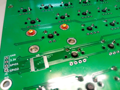
First up, the new boards arrived :) I ordered these from PCBWay as usual, and they were of the expected quality and finish:


One of the main differences between this and the original revision of the PCB, is the inclusion of the mounting holes for the key stabilisers.  I wasn't 100% sure of the hole sizes and spacing of these, so I wanted to check this first.  There are only two stabilised keys on the MEGA65 keyboard: RETURN and the huge 170mm long space bar:

So the RETURN key stabiliser was fine, which was a good sign. Then onto the space bar.  This one is a bit trickier, as I wanted to allow for both DIY keyboards using easily available key caps, which means a 6.25x space bar, as well as using official MEGA65 key caps, which includes the lovely 9.0x 170mm wide space bar.  The stabiliser kit I bought only had wires for 6.25x, not 9.0x space bars, which is not unexpected.  Not a problem: We will try first with the 6.25x space bar I pulled off a random mechanical keyboard that was laying around:

That looks fine, too.  Now to put the key caps on both the space bar and RETURN key to check that everything really fits and moves smoothly:


Both worked just fine, and had a really nice solid feel to them.  Now it was time to look at the MEGA65 9.0x space bar. Without the stabiliser wire, I could only test the alignment of the stabilisers, which is not a problem, as its then just a case of folks cutting the right length wire and bending it up into shape. Thus the main thing to test was the spacing of the stabiliser holes, which as we can see here, are just fine:

With this preliminaries out the way, I proceeded to solder in all of the key switches, so that I could do a full "dress rehearsal" for fitting the keyboard into a MEGA65 top case, as I wanted to check if I had corrected all the screw hole positions:
With the soldering done, I installed the stabiliers again, including screwing them in place.  My landing pads were plenty big enough for this, which was nice:
Then it was 20 minutes of transferring key caps from the MEGA65 keyboard to this one.  Those who read the post about the first revision of the DIY keyboard will be pleased to see that the RETURN key can now be installed, because I got the position fixed on that :)

Then I installed it in the top case, and screwed it in. You really can't tell that its not the original keyboard now, which is exactly the goal!

I also made sure that all the keys pressed and released without snagging on the case (which is a problem that the original C65s had), and all was well there.

I was using only 5mm spacers instead of 6mm spacers, which made this test more rigorous than real life.  In the process of all this, I did notice that the keyboard is not exactly centred in the cut-outs, as can be seen in the following two photos: Basically the keyboard should move about 0.5mm left, and maybe 0.25mm up, to get it perfectly centred:


That is really the only issue I identified with the physicality of this revision.

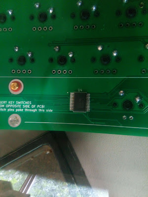
Now, so far we had only the keys installed, not the other components to make it work.  There were only a few minor schematic changes, but safe is safe, so I set about installing the those.  I only had the components I had installed on the original revision of the DIY keyboard, so I used my hot air rework station to pull those off, leaving a rather sad looking board, and not just because the focal performance of my phone camera is about as reliable as the weather:

I then had my little treasure-chest of I2C IO expanders and SMD LEDs:
I used a combination of hot-air and hand-soldering, including drag-soldering, to put these onto the new board.  I found I was generally "less bad" at doing this, than the first time around. I had only a few bridges and dry joints to re-work after the assembly.


Then it was time to test.  This revealed those dry-joints I mentioned, and also that I completely missed soldering one of the key switch pins. That got all keys responding. The two keys I had changed the connections of from the previous revision turned out to be swapped around, so I did a quick fix to t he VHDL to solve that, and then it was all working. Yay!

Now all that's really left is to generally clean up the PCB routing, so that the traces look nicer, and fix those slight positioning problems of the keyboard. It's already close enough that anyone with a Nexys 4 / Artix 7 board who wants to build a real MEGA65 keyboard to use with their FPGA board could safely do so.

At this point, I'm handing those tasks over to the community, so that I can focus on finishing bringing up the MEGA65 Expansion Board, with its composite video, user, tape and C1565 ports.

Monday, 21 November 2022

Progress on the DIY Keyboard

As I have explained in recent blog posts, I am working on an alternate PCB design for the keyboard, with a couple of goals, the chief of which is to make it possible for folks to build their own MEGA65 keyboard at home for use with off-the-shelf FPGA development boards.  It also creates an insurance policy for us for production of the keyboard for the retail MEGA65s, because the design doesn't use any FPGAs that are impossible to source, but rather a bunch of easily sourced I2C IO expander chips. 


Previously I had gotten as far as getting the PCB designed and fabricated by PCBWay. The last week has been focussed on populating the PCB with keyswitches and the other vital components, and then adding support for it.

Assembly wasn't too tricky, as the surface-mount I2C IO expander chips are fairly easy to place using drag soldering, and then cleaning up the bridges after using solder braid. There are lots of YouTube tutorials on how to hand-solder SMD components in this way. If you are lucky enough to have a reflow oven, that would work fine, too, of course, but it isn't necessary.  

The key switches themselves are super easy to click into place (just make sure they click in all the way and sit flat on the PCB). Because they click into place, you can populate the whole board in one go, and only after flip it over to solder all their legs in place.

Apart from that, there is only the 10 pin hole-through header and some hole-through resistors to get the core of the keyboard working.  

That got things far enough that I could start trying to add support to the MEGA65 core for this.  After a frustrating couple of days where it looked like the rise-time on the I2C bus was ~50usec instead of ~500ns, I finally realised what I should have already remembered: The keyboard connector routes via the MAX10 auxilliary FPGA on the MEGA65 main board.  Once I remembered this, it was actually a good thing, as it meant that I could just resynthesise the MAX10 FPGA with support for the keyboard, rather than having to wait an hour or so each time to resynthesise the core for the main FPGA.  It also means that none of the existing cores will need modification to support this keyboard, as it is only the MAX10 FPGA program that needs updating.

With that problem out the way, it was time to actually pull it all together.  As the keyboard bus has proven a bit fiddly to work with in the past, I implemented unit tests that included the MAX10 FPGA, the keyboard FPGA on a MK-I keyboard, and the I2C IO expanders of the MK-II keyboard, as well as a simple representation of the Xilinx FPGA's side of the keyboard communications. This let me test the entire system -- including auto-detection of the keyboard type -- offline and quite quickly.

This meant that when I did synthesise an updated MAX10 FPGA bitstream, it actually worked first time -- the only outstanding problem was mapping problems with various keys (which I expected), and one last little I2C communications problem that didn't show up during simulation.  It really did make my life much easier.

Most of the IO Expander ports were backwards compared to what I had listed, which is probably just a transcription error on my part. But I did discover that I hadn't properly wired up the E and <- keys. Fortunately I did include a GPIO header with a couple of spare lines, so I have connected those keys to those, and then re-mapped the GPIO lines to where those keys were originally intended to go. This means that I can make these "revA" keyboards work with all keys, without introducing electrical differences in the "revB" that will include fixes to all the problems I have identified along the way.

The fixes for these two keys are the only changes that have required "bodge wire" as I call it on the revA PCBs:


Add some key caps I had laying around from an old mechanical keyboard to make testing easier, and I had something that more or less works:

Obviously you would want to get a proper set of keycaps for it if you were building it yourself -- but, again, if your goals was to spend just a little each time, and progressively improve your home-made setup, then you could totally do something like this.

With that I was able to use the MEGA65's on-screen-keyboard overlay to confirm that each and every key was working.  It did also show up that I still had one solder bridge to clean up, as the F and SPACE keys were both causing both to be pressed.  By cross-referencing back to the schematics I was able to quickly identify the location and clean it up, resulting in a completely working keyboard after that.

So, that now just leaves getting all the LEDs working, and confirming that the LOCK keys are doing their jobs.  SHIFT LOCK I know is already working fine, because I can see it toggle the SHIFT LOCK key on the on-screen-keyboard.  The CAPS LOCK key is trickier, because it also doubles as the "turbo" button: Hold it down, and the CPU goes full speed.  I have also still to confirm that any of the LEDs work, and that they are the right way around.  This goes for both the LOCK LEDs, as well as the power / drive LEDs at the top.

I'll start with the SHIFT LOCK LED, as that should be fairly easy to deal with.

The IO expander that drives the LEDs has to be switched from input to output mode, which happens only once when the MAX10 first detects the MK-II keyboard.  This means that if the keyboard is detached and re-attached, thus powering down the IO expanders in the meantime, that the LEDs won't work.  To avoid this situation, I just need to flash instead of program in the updated MAX10 bitstream, and not unplug the keyboard.

Having done all that, I'm still not seeing the LOCK LED get any voltage on it when I toggle the SHIFT LOCK key.  Ah, that could well be because I haven't yet fitted the 330 Ohm resistors for the LEDs :)

So now I have the SHIFT LOCK LED working, but its inverted: On when the LOCK if off, and vice-versa. Easy to fix in the VHDL. CAPS LOCK is the same, but it also has to do the tricky "cancel last CAPS LOCK toggle if held down for a long time" feature, that we use to make CAPS LOCK a convenient "TURBO" button.

All that's left now, is the power and drive LEDs. So far I only have one of the four fitted, and the resistors for one of them as well.  The logic is in theory all there for doing Pulse Width Modulation of the LEDs to allow brightness control of the R, G and B channels for each.  I have of course not fitted the matching LED to the resistors. I should really just fit the remaining LEDs and resistors, and then go from there. In theory the power LED should come on when the keyboard is connected, without further work, although I suspect I have the control sense of the LEDs inverted, i.e., off is on and on is off. We will soon see!

With resistors fitted, the LED that is currently fitted is working, and not emitting smoke from excess current, so I now feel safe to fit the other LEDs.  The colour selection is indeed inverted it seems, with the drive LED showing blue. I've now fitted the remaining LEDs. They are quite fiddly to hand-solder, but I think I have them in ok.  Certainly 3 of the 4 are nice and bright -- if not a little too bright. The 4th I think I just haven't got soldered down particularly well. I'll fix that a bit later.

It looks like I had the LED order reversed, and also the red and green channel of each reversed. This is not particularly hard to fix, so I'll deal with that now.

Meanwhile, the only feature this keyboard lacks compared with the MK-I, is the "ambulance light" mode when the main FPGA is not talking to it.  In fact, it would work even if the MAX10 FPGA was not talking to it.  However, for the MK-II keyboard, the MAX10 is doing the talking to the keyboard, so we can still detect the lack of communications from the main Xilinx FPGA, e.g., when there is no valid bitstream/core loaded on it, but not if the MAX10 is sad.  That's probably still a reasonable gain over not having it at all.  This of course won't work on other boards like the Nexys4 if we add support for this keyboard to it, because there will be no communications at all.

And after the usual fiddling of getting the RGB order "fixed" in a different wrong order, I now have it all back and working.  Also, because of the way the MAX10 is involved in driving the MK-II keyboard, it is also safe to return to having red and blue flashing lights for Ambulance Mode, which I think always looks nicer.

Before I wrap things up, I also wanted to make sure that this new keyboard handling code in the MAX10 correctly handles the original MK-I keyboard, still. This is where my "hot auto-detection" code is handy: I can switch the keyboards at will on a running machine (don't do this at home, as it isn't totally risk free), and the MEGA65 adapts to the appropriate keyboard, and I can keep typing merrily away on the switched keyboard within about 1 second of plugging it in.

Now I think its time for a video showing the whole thing together.  I've just done a live stream on twitch, which I'll embed in here once it's up on youtube. The audio is a bit quiet in the first few minutes, but I fix it, so persevere, or just jump to around the 5 minute mark.


With everything working, it's now safe for me to finish revising the PCB design, ready to get some more samples made, so that I can do a repeat assembly test, and confirm that everything is fine. I had a bit of a TODO list of items for that, including tweaking mounting hole positions, using larger resistor footprints, so that they can be soldered flat to the board, as well as adding the supports for the RETURN key and SPACE bar.  

Those are all done now, and I now just need to be able to confirm their correctness.  The best way would be to print at 1:1 scale, so that I can fit-test, but I've yet to find a way to get KiCad and my printer to come to an agreement on how to achieve this.  I've also ordered some keyboard stabilisers, so that I can confirm that I have the correct PCB mounts for them.  So that's it for now, until the stabilisers arrive, and I figure out a good way to fit-test the changes.

Wednesday, 16 November 2022

Working around 74LVC165 supply problems for the MEGA65 Expansion Board

I mentioned in a previous blog post I mentioned that the expansion board was designed around using the 74LVC165 shift register for reading the IO lines. Unfortunately, they are a bit of Unobtainium right now, but the 74HC165 is available, and is 5V tolerant. 

However, if you run them on 3.3V VCC as I am doing to get 3.3V shift register output for input to the FPGA, then if the IO pins are at 5V, the voltage difference leads to current flowing continuously through.  

This can be solved by putting resistors in-line with the IO pins, to limit the current.  a 1K resistor will mean that with the 5V - 3.3V = 1.7V difference, that 1.7V / 1K = 1.7mA of current will flow -- well below the 50mA limit of the 74HC165s.

So the next step was to patch the boards to have these resistors in line.  This turned out to be a pain, so I instead just designed a little PCB that could be inserted into the 74LVC165 sockets, and have a socket on it for a 74HC165 and the resistors inline.  I made it a super simple 2-layer board, so that I could get it fabricated quickly by PCBWay. 

Those little boards arrived today, and I assembled three of them, and inserted them into the test expansion board I have been building:


So the next step will be to test this. But first, I want to finish working on the MK-II keyboard. I've got that mostly assembled now, and will do a blog post on my adventures and misadventures working on that.


Sunday, 30 October 2022

Let's start doing something about those missing expansion ports

The MEGA65 case has a bunch of cut-outs for ports that we didn't include on the motherboard, to prevent the cost from being increased more than necessary. But by putting those cut-outs into the case, and providing the supporting screw bushes in the bottom of the case, we have the ability to easily design a PCB that can provide the missing ports.

No longer will this area of your MEGA65 need to look so empty.
 

I've been learning Kicad, the free PCB design software lately, and have made an initial design for an expansion board that would provide all the missing ports: user port, component video, C1565 external disk drive, and C64 tape port.  This means that we have all of the ports that a C64 or a C65 had: The C64 obviously didn't have a C1565 port, while the C65 lacks a tape port.

The main challenge for designing such a board is that we don't have a huge number of spare IO pins on the MEGA65.  We basically have the two PMOD ports in the trap-door slot, which give a total of 16 IO lines.  So we have to work with those.  They are also not super ideally positioned, but we will have to live with that.  A pair of ribbon cables with headers on the end, or perhaps a little adapter PCB that provides the necessary connectors and connections will be possible solutions. For prototyping, I'll just use a gaggle of jumper wires.

Getting component video and audio working will be the main challenges, and the solution I have devised is quite experimental for this: I am using 4-way resistor ladder DACs for chroma, luma and audio.  These will be clocked at something like 40.5MHz, or perhaps even 405MHz using SERDES from the FPGA, so that we can get much more than 4-bit resolution.  It's possible the initial design will have incorrect resistor values to get the correct voltage range, and that it might all require a bit of tweakage. But that's what prototyping is for!

Having chroma, luma and mono-audio with 4 bits each consumes 12 of our 16 pins, which is annoying. So we need a very low pin-count solution.  I could have used I2C, but have instead opted for using discrete 74LS and 74LVC logic chips, mainly serial shift registers.  There are a few reasons for this: 

1. The 74LS/LVC chips are readily available, even while Chipaggedon rages on (for now, at least). 

2. Having a bunch of DIP chips inside your MEGA65 case will have a nice retro feel to it.

3. I want this board to be able to be hand-soldered by just about anyone, so this means no surface mount parts.

This means that our interface consists of a clock from the MEGA65 side to the shift registers, and a data out and a data in line. That makes 4 in total, which is exactly what we had left over after our three DACs.

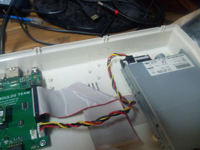
Some further tricks I have done to reduce the pin count, is to make the C1565 port get a number of its data lines from the 34-pin floppy connector. This is why the expansion board has 2x 34-pin floppy connectors: One goes to the MEGA65, and the other to your internal floppy drive. The two connectors are just pass-through between them. I similarly provide two floppy power headers: One to get the 12V we need for the tape port power supply (the tape drive requires 6V DC) as well as the 5V we need for a bunch of the logic chips, and the other so that you don't end up with one less power connector, if you had some other use for it in your MEGA65.

Here is what the design looks like:


The two funny cut-outs are to make it easier to your your floppy cable from the edge of this board under the internal drive, and then to allow  the cable to re-emerge to enter the back of the internal drive.

In volumes of 100 units, the bare board should cost less than US$15, and the parts probably another US$50 or so.

Otherwise, there probably aren't too many surprises with this board. Prototyping will let me check that the design works, add support for it to the MEGA65 core, and also make sure that I have all the measurements and port positions correct.

The source for it will be up soon at https://github.com/mega65/mega65-r3-expansion-board. But it is marked private for a couple of weeks, because some of the commits would otherwise spoil another surprise I have in the works.  But be assured, they will be available soon.  This PCB will be complete open hardware, meaning that the gerbers and everything else you would need to make one entirely on your own will be available there.

What I would love in the meantime, is anyone who would like to help me with the prototyping and testing.  Between this, the keyboard, and the other surprise PCB, I've put a whole pile of time as well as PCB prototyping production costs in lately, and it would be great to have some assistance with getting this all working.  I'd love for folks to be able to buy the parts for the expansion board before Christmas this year, to have something fun to work on on their MEGA65s over the break.

Saturday, 29 October 2022

MEGA65 MK-II Keyboard PCB Design

Chipaggedon is still raging. The little FPGA we use in the MEGA65's keyboard has a lead time of 90 weeks. This shows just how crazy things have gotten. But we don't want to wait 90 weeks before we can deliver a 3rd batch of MEGA65s (the keyboards are already there for the 2nd batch, don't worry!).

So today I set about designing a new keyboard PCB for the MEGA65, that doesn't use an FPGA or any other components that are impossible to source at the moment.

To add to the challenge, I want the new keyboard to be able to work on existing MEGA65s, and vice-versa, so that there is minimal drama in making the switch.

Finally, I want it to be easy to build yourself, so that folks with a Nexys/Artix FPGA board can one day make a MEGA65 keyboard to connect to those boards.

My weapon of choice for PCB design is Kicad, because its open-source and really good. I've been learning to use it lately on a couple of projects that will be revealed in the fullness of time. But for now, we'll focus on the keyboard PCB.

To avoid the FPGA, and stick to the 3 wires available for communicating with the MEGA65, I have picked an I2C-based IO expander chip. These chips each have 16 IO lines, with internal pull-ups, so I don't need any resistors for that on the board. They also have 3 address straps, so that I can have up to 2^3 = 8 of them.  As it turns out, I need only 6: 1 for the RGB LEDs and lock key LEDs, and 5 for the 78 key switches.

These chips cost only about AU$3 each in small quantities, so we are talking AU$18 or less for them all -- which is about what the little FPGA costs in similar quantities. I expect in modest batch quantities these I2C IO expanders will be AU$2 or less each.  

One of the cost savings that using 6 of these chips is that we don't need to use key switches with internal diodes, or to supply diodes on the board. This also makes the design much less work to build yourself. There is about a AU$0.20 saving per key switch by getting the diode-free key switches, so over 80 keys, we are talking about AU$16 in savings -- i.e., the IO expanders quite literally just about pay for themselves.

A plus side of this non-traditional approach, instead of using a matrix with diodes, is that there is no limit to the number of keys that can be held down at once, as each of them has a separate wire.  The I2C protocol at 400KHz should allow sampling the keys and updating the LEDs at >1KHz, i.e, less than 1ms delay, which should be fine.

The code is all at https://github.com/mega65/mega65-kbd-pcb, if anyone would like to take a look.  Here are renders of the board from front and back:

I've tried to provide helpful information for assembly and sourcing on the board, make it as easy for people to build up as possible.

Next step for me is to get some PCBs made up, and try to assemble one.  This will reveal if I have any placement errors switches or mounting holes. I've very carefully measured it all, so hopefully it will be fine.

On that, because one of the goals of this is to make it easier for people to build their own low-cost MEGA65, I'll try using some Cherry MX clones, instead of real Cherry MX key switches. A set of those can be had for about AU$40, including postage.  So add AU$18 for the chips, and probably AU$10 for the PCBs in batches of 100, and about AU$10 for the remaining parts, and we have a keyboard that can be built in small quantities for AU$68, excluding the key caps.

But that's it for today, while I wait for the PCBs to arrive.


Monday, 17 October 2022

DIY USB JTAG and UART connection for the MEGA65

The best way to connect to a MEGA65 from a PC, is using the TE0790-03 FPGA JTAG Adapter from Trenz Electronic. There are several reasons for this:

1. They are the adaptor that the MEGA65 was designed for.

2. They are really fast. You can flash a bitstream onto the MEGA65 in just a few seconds.

3. The one USB connection does both UART and JTAG, so you have less "cable salad".

4. The MEGA65 m65 and m65connect tools fully support it.

5. Xilinx's Vivado FPGA development suite also directly support it.

However, with the COVID19 "Chipageddon" silicon supply problems, they aren't always available.  So we had a think about how to let people connect a USB UART or JTAG adaptor without the TE0790.  

We already have one solution to this, where you can use a TEI0004 from Trenz Electronic with the MEGA65's m65 and m65connect tools, by connecting it via a special adapter board that I designed. Those adaptor boards are available to buy, but the TEI0004 is also affected by Chipaggedon, and isn't always available. So we need yet another solution.

Together with some folks on the MEGA65 discord server today, I worked out that a clone of an Altera USB Blaster JTAG adapter can be used with our adaptor board, to connect to the MEGA65 and control it via JTAG.  With the openFPGAloader program it is possible to push a bitstream to the MEGA65, by connecting it up like this:

and then running a command like this:

$ time -p sudo ./openFPGALoader -c usb-blaster ../mega65-core/bin/mega65r3.bit
Open file DONE
Parse file DONE
load program
Flash SRAM: [===================================================] 100.00%
Done
real 10.75
user 0.01
sys 0.03

The astute will notice that we are using an Altera cable to flash a Xilinx FPGA -- thanks to the wonder that is vendor-agnostic open-source software development!

So that gets us half of the solution using just a cheap USB blaster clone like these, that can be purchased for less than AU$5. 

What that solution is missing, though, is a USB UART, and the means to connect it.  There are few different options here.  I'm leaning towards a PL2303TA-based USB UART like these, because they are dirt cheap (less than AU$2), and should do all that we need, and already come with a USB cable, so that you don't need to make an extension lead between the MEGA65 and PC. I've ordered one from local supply here in Australia, and even with courier delivery to speed it up, it was still less than AU$15, all inclusive.

All that's left is to modify the adaptor design to have a break-out header that the UART pins can be connected to.  Then it will be possible to assemble this whole solution from a hand-ful of low-cost components.  So time to open my KiCad PCB design for this board again, and add the connector.

I'm tempted to do this by just adding a 2nd 10-pin connector, since I already have the male headers for those, and it gives maximum flexibility and least effort on my part as well. Or I might get excited and make the header compatible with one of the common FTDI pinouts, so that people can use one of those, if they have one laying around.  Unfortunately there are about 4 such pin-outs to choose from. So if I do that, it will be based on whichever model I have lurking on my bench here. 

In the end, I decided to just add a 3-pin header with GND, TX and RX pins. I will mount this on the underside of the PCB, so that it doesn't interfere with the J2 connector when occupied.

Here is the revised schematic and PCB layout:


It's still all super-simple.  I've submitted an order to PCBWay.com for 50 (the postage is still more than the PCBs for 50 units, because the board is so small).

So now its waiting a week or so for the PCBs and the USB UART to turn up, before I can do the next step.

It's now a week later, and the PCBs have arrived, and I have assembled a couple to test with:

The white wire on the PL2303 USB UART adapter goes to RX, and the green wire to TX, and black to GND, like below. Red doesn't connect to anything. But note that if you are using a different model of USB adapter, they will likely have a different pin out. Research and check it before connecting, so that you don't accidentally kill your MEGA65 by feeding 5V or worse down the JTAG header.

Connected up, it looks like this:

At first I couldn't get the UART working, but it turns out that some USB Blaster cables clamp the pins that the UART is connected to. The solution to that problem is to snip the two pins on the header where the USB blaster or TEI0004 connects, so that they don't connect into the USB blaster:


With that done, you can safely plug both a USB UART and the USB blaster in at the same time.  

The m65 command doesn't yet know to push bitstreams over JTAG using the USB blaster cables, so for now you have to use openFPGAloader to do that, as described above.  However m65 can happily talk to the USB serial cable, but you do have to provide the name of the port, as m65's auto-detection doesn't yet support detecting these cables. So for example, if you wanted to switch to C64 mode, you would use something like:

$ m65 -l /dev/ttyUSB1 -4

We will likely fix both these things in m65, so that it has transparent support for the adapter. The same goes for m65connect.

So now we have a nice cheap solution to get serial monitor interface and JTAG pushing of bitstreams, that is still available even when the TE0725-03's aren't in stock with Trenz Electronics.  The TE0790 is still a nicer solution, as it is just one USB cable, has faster JTAG, and is supported by Vivado and other toolchains, but it's nice to have the fall-back.


Saturday, 8 October 2022

Adding proportional text support to the MEGA65's "web" browser

In the previous post I sorted out the Ethernet and TCP stack bugs that were preventing the browser from working, as well as getting some of the general infrastructure in place, like having a start screen for the browser, that lets you choose the initial URL to open.

What I want to work on now, is improving the appearance of the pages.  The H65 format allows for using almost all of the MEGA65's graphic features, but my current page generator doesn't really support any of them, except for underlined text and in-lined images. In particular, text is restricted to using the normal C64-style 8x8 fixed width font.  That's fine for starting, and its also good to have that font available for where it makes sense, e.g., for showing BASIC code snippets.  However, it would be nice to be able to use much nicer looking fonts in pages as well, if people want to.  

Fortunately, I have done quite a bit of work on displaying proportional fonts on the MEGA65. In fact, we have MegaWAT!?, a power-point like presentation program for the MEGA65 that renders proportional text in real-time on the MEGA65. In fact, I've even given presentations at conferences using it and a real MEGA65 instead of a boring normal computer. So I already have C code for reading TTF or Type 1 fonts using libtruetype on Linux to create rasterised fonts that the MEGA65 can display.  In fact, for the browser its even easier, as we are generating the H65 files on the server-side, so we can do all of the rendering there.

What will remain the same, though, is that we don't just render the fonts onto a big fat canvas, as that would waste lots of precious chip RAM, and limit the size of pages that can be displayed.  Instead, we convert each glyph from a font into a set of 8x8 FCM characters that the VIC-IV can display. We can then just assemble the glyph each time we want to display it using the same FCM character definitions, thus saving lots of RAM. 

This would mean that all the glyphs would have to be a multiple of 8 pixels wide, which kind of defeats the purpose. But here the VIC-IV in the MEGA65 has a secret weapon: In 16-bit text mode, you can tell the VIC-IV to only draw a variable number of the pixel columns of a character. This makes it nice and easy to display glyphs from fonts that aren't exact multiples of 8 pixels wide.  Thus we can still get the nice appearance, without wasting the memory. 

The second secret weapon of the VIC-IV is the ability to use FCM characters in "alpha blending mode", where instead of allowing each pixel of a character to be chosen from the 256 colour palette, we instead use that value to indicate the fade value between the foreground and background colour of the character.  For example, if the background colour were black and the foreground colour were white, then a pixel value of $FF would display white, and a pixel value of $00 would display black, and a pixel value of $80 would display a colour half-way between them, i.e., some shade of grey. This allows text to be anti-aliased and look much better.  Best of all, it doesn't use up any palette slots on the VIC-IV to do this. 

The third secret weapon is that instead of using FCM + alpha blending mode, we can use NCM + alpha blending mode. This means each 64 byte FCM char block encodes a 16x8 pixel area instead of an 8x8 pixel area, thus reducing the number of char blocks required to display larger glyphs.

By combining all three of these, I intend to support really nice looking text in the MEGA65 browser, like this:


The first step is to modify the md2h65 converter to allow the use of these fonts. This involved pulling a pile of the code from the tool used to prepare fonts for MegaWAT!? into md2h65.  I then had to re-factor the md parser I had made, as it was pretty rubbish, and couldn't support UTF-8, or even properly support most of the mark-down formatting strings. 

Markdown doesn't include a native way to specify typefaces, so I have hacked in a C-inspired syntax that allows declaration of different typefaces for the different text types. These lines look like this:

#define FONT(p) /usr/share/fonts/type1/urw-base35/NimbusRoman-Italic.t1,16

The p in brackets means paragraph, and in addition we also support h1, h2, h3, bold, italic and bolditalic to override all of the fonts.  The ,16 at the end indicates the size of the typeface.  At the moment, the font name has to be the absolute path to the font file, but I hope to improve that along the way.

Next, the renderer in md2h65 has to assemble the lines of text that might be a mix of C64 font and these proportional fonts, all of which might have different heights.  I already had code for mostly handling that in MegaWAT!?, which I also hacked into md2h65.

Initially I haven't implemented the trimming of the character widths, as I just want to make sure I have the font rendering working.  One challenge with debugging this, is that the m65 utility that I use to render screen-shots of the MEGA65 for these posts doesn't yet properly handle the alpha blending mode, so I have to bug fix that.  I then also hit another random bug in the network code, causing some corruption of the received TCP frames, which is confusing the browser code, so as usual, I have to go down a few rabbit holes, before I can progress.

Specifically, a byte of the H65 file is being mutated from $00 to $06 at some point during either network handling, or in my parsing the H65 in the browser code. I can see it is modified in the RX buffer of the TCP socket when it is being parsed.  So now to find out when it is being corrupted...

And it looks like the contents of the Ethernet frames are being corrupted, as I am seeing things like this:

00000000: 53 65 72 76 65 76 3a 22 53 6b 6d 74 6c 65 48 54    Servev:"SkmtleHT
00000010: 54 54 2f 36 2e 36 20 50 79 74 68 6f 6e 2f 32 2e    TT/6.6 Python/2.
00000020: 37 2e 31 38 0d 0e 44 65 74 65 3a 22 53 61 74 2c    7.18MNDete:"Sat,
00000030: 20 30 38 20 4f 67 74 24 32 30 32 32 20 30 33 3a     08 Ogt$2022 03:
00000040: 33 32 3a 37 35 24 47 4d 54 0d 0a 43 6f 6e 74 65    32:75$GMTMJConte
00000050: 6e 74 2d 74 79 70 65 3e 20 61 70 70 6c 6d 63 61    nt-type> applmca
00000060: 74 6d 6f 6e 2f 6f 63 74 65 74 2d 77 74 76 65 65    tmon/octet-wtvee
00000070: 6d 0d 0a 43 6f 6e 74 65 6e 74 2d 4c 65 6e 67 74    mMJContent-Lengt
00000080: 68 3a 20 31 34 37 38 33 32 0d 0a 4e 61 73 74 2d    h: 147832MJNast-
00000090: 4d 6f 64 6d 66 6d 65 64 3a 22 53 61 74 2c 20 30    Modmfmed:"Sat, 0
000000a0: 38 20 4f 67 74 24 32 30 32 32 20 30 33 3a 33 32    8 Ogt$2022 03:32
000000b0: 3a 33 38 20 47 4d 54 0d 0a 0d 0a 48 36 35 ff 27    :38 GMTMJMJH65~'
000000c0: 00 50 85 54 e8 37 00 06 06 07 f0 c9 00 00 00 00    @PETh7@FFGpI@@@@

For example.. "Servev" should most likely be "Server". 

So why is this suddenly happening now?  Ah, I am still running the old broken bitstream for some reason... Ah, that would be because I updated the bitstream in slot 0, but didn't erase the old bitstream in slot 1. Well, at least that's a simple problem, and means that I haven't got any new network bugs to deal with.  

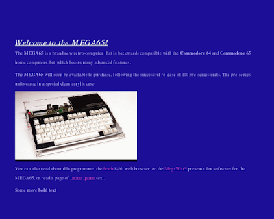
Okay, so that's all fixed, and I can load pages again.  So now to test the NCM rendered proportional text. Initially I have just a single word at the end of the test page that is in a proportional font, the word "Some".  Without aliasing, it looks a bit messed up, but you can still see what it is:

On real hardware, the background of those gylphs is blue, not black. This is part of that bug in the m65 screenshot renderer I was saying out. So let's fix that first. Righty-oh, now can see it properly:

Again, note that I haven't yet implemented the character trimming. There is also some artefacting around the alpha blended characters in the screenshot that is not visible on the real hardware, which will be easy enough for me to fix.

Done:

Much nicer. Now to implement the width trimming.  I also noticed that my renderer incorrectly things that C64 font text is two lines high, as well, which I'll have to deal with. But first the width trimming:

That's looking nicer.  But we have some "poop" on the right-most edge of the glyphs. I'm guessing I have an out-by-one error there somewhere, which should also be fairly easy to fix.

It turned out I was just not trimming by enough. With that corrected, that single pixel column of poop goes away. Quite why it is even getting into the char blocks though is still a bit of a mystery that I would like to solve. In theory, I'm only copying those columns indicated as part of the glyph. Ah! It's because in NCM mode, I am packing two columns of pixels into a byte, and I don't check if the char is an odd number of pixels wide. So now it looks like this:

Good. Now that single word looks right.  Let's get multiple words working. At the moment we have a problem where each word appears on a separate line of its own, like this:

"Some" and "more" should be next to each other, and "bold text" should also be next to those.  That "bold text" which is just C64 font ends up on a new line tells me that the problem is that a new line is being triggered when outputting proportional text.  This problem was that I wasn't first rendering the word to measure its length, but rather just feeding it out as a line. Probably just from when I started implementing it.  But now with that fixed, we get this:

That's looking more right, except that we aren't emitting spaces following the proportional text words. With a bit of re-factoring, we now have spaces of the correct size proscribed by the fonts:

Now its time to tackle that extra vertical space. That problem was that I was incrementing the Y position during rendering the lines, and then again after the line of text had been rendered: Only one of these is required. With that fixed, its looking right again:

We are now quite close, because we can now assemble whole lines of proportional text. So I'll modify my example MD file here to use the proportional font for all of the paragraph text, and maybe also set some fonts for the headings, bold and italic, and see how it looks. 

And all the text has disappeared, which is very odd!

So why is this so, when we had some proportional text working before?  Also, the spacing makes it look like it wants to display the text, but is messing up some how.

Looking at the binary of the H65 file, it looks like it is outputting the right number of glyphs, just that they are all blank.  The problem is stemming from loading more than one font. If I have only one font, then life is good.  Any more than one font loaded via #define FONT() directives, then they all come out blank.  So I must have some problem with my handling of font loading. With that fixed, we have some progress:

We can now see text in the different typefaces, but with some obvious problems:

1. The rows get out of sync when characters are of different heights.

2. The underline attribute is being applied to all rows, not just the base-line row.

3. There is still some problems with some text being invisible or generally messed up.

4. The reverse attribute shouldn't be applied to bold text that uses a proportional font.

There are probably some more in there, too, but that's a start for me to work on.

For the out-of-sync problem, I just need to apply the trim to all rows of chars in a glyph, even if they are out of the range used by that glyph. This is a little fiddly, because we can mix 8x8 C64 chars with 16x8 glyphs. So we need to explicitly code these gaps as empty glyph blocks with trim.

Some progress:

Problems 1 and 2 are now solved. I can also now see another problem:

5. The underhang of characters is not drawn, e.g., the tails of g and y characters.

But what I most care about right now, is that large slabs of the text is invisible.

This is a bit weird, as there doesn't seem to be any real pattern to what gets displayed, and what does not. It looks like the problem might be in md2h65, as the blank sections do seem to be really blank in the H65 file. Ah, the problem was I had setup some buffers with incorrect dimensions. Now it is better:

So that solves 3, leaving 4 and 5.  Hopefully getting the descenders of glyphs to display won't be too hard, as they are being rendered.  Again the problem here was just some mishandling of the buffers and addressing of the rows in them.  So now we can see the descenders:

That's 5 done, just leaving the disabling of the reverse video for bold face when using a proportional font.  That will be easy to fix. I should also allow selecting different colours for the various type faces, as well. But first, removing the reverse video:

Well, that's really starting to look quite nice and elegant. I'll get to the colours soon, but there is a more pressing issue here: This particular size of font, 10pt, is a really poor choice, because of two reasons:

1. The glyphs all tend to be less than 8 pixels wide, which means that we run out of our 80 columns of characters before the right edge of the screen. As a result, the lines of text don't go all the way to the right.

2. Because of how we draw the proportional text using VIC-IV characters, the text has to be a multiple of 8 pixels tall. 10pt tends to have ascenders that are 9px tall, and descenders that are 1 or 2px below the baseline. As the characters are aligned on the baseline, the result is each line of text occupies 3 character rows, which leaves a lot of space.

So the simple solution is that we can use a larger font size, so that the white-space is reduced.  Later we could look at having the page layout configurable, so that fewer lines with more characters are possible. Another approach is to render pairs of glyphs into single character boxes.  Given how common certain pairs of letters occur in most languages, that's probably a fairly workable solution.  This would only be needed for typefaces that are being rendered at less than about 16px.

With that done, we can now fill lines up fairly comfortably, as we can see here:

Now we can see a new problem, that we are breaking lines in the middle of words.  This is a bit odd, as the word rendering logic is still supposed to be fixed to whole words. That is, it should try to place words on one line or the other, and not even be able to split them, even if it wanted to.  So how is this happening? Ah, when I refactored, I had the word render output on the wrong side of the moved loop boundary for the di-glyph grouping.  

With that fixed, now its better:

The grouping of multiple glyphs into single 16x8 character cards is actually pretty nifty. It's even combining some of the characters in the larger typeface in the heading.  It will be interesting to see how it fares with larger slabs of text, where the proliferation of di-glyphs might mean that it uses more of the limited number of character cards available.  We'll have to see.

A more pressing issue right now is that it is only by sheer luck that this change has made complete lines fit almost exactly.  If we used a slightly larger typeface, the lines will start to run off the right-hand edge of the screen, because they will be averaging more than 8 pixels per character card. That isn't happening right now, because the spaces between the words are not merged with other glyphs, and help to bring the average width of the character cards back down to almost exactly 8.

If I increase the stuffing of glyphs into the character cards to require at least 11 pixels instead of 8, then the average pixels per card will increase to be greater than 8, and we'll see it start to run off the edge, like this:

The solution is to track the number of display pixels on an accumulated line, rather than the number of characters, and just assuming that they are all 8 px wide, like on the C64.

With that fixed, we now have nicely filled lines, with no overrun:

So now it is super easy to modify the sizes of the fonts:

Really all that's left for this part, I think, is to move the text one pixel above the baseline, so that the underline appears in a more sensible place, and think about how to reduce the number of dead char rows.  Moving the baseline would be enough to help for fonts that have only 1px descenders.  For larger sizes, maybe we make a trade-off and have the under lining below the descenders, in return for being able to reduce the maximum dead-space below the descenders.  But that will have to wait for another day.  For today, I'm just pleased to have advanced from previous state of being able to use only 8x8 fixed-width bitmap fonts to having really quite pleasant and readable looking text -- especially for an 8-bit machine.