
The MEGA65 case has cutouts for a few ports that we didn't include on the original motherboard, to keep costs and complexity under control. Avid readers of this blog will know that I have designed a prototype expansion board for the MEGA65 that is intended to provide those missing ports. In this blog post, I am documenting my efforts on getting the composite/s-video output working.
To keep life simple to begin with, I am implementing a pure luma signal first. This is the monochrome grey-scale output, which contains the HSYNC and VSYNC information, as well as the brightness of the pixel data. The result should end up looking something like this:

Keep reading if you would like to find out how I got to that point...
The expansion board uses a very simple and cheap 4-bit resistor DAC to generate this signal, thus allowing up to 16 levels of brightness, unless I succeed in my cunning plans to allow over-sampling in one way or another. The PAL/NTSC video standards use 13.5MHz pixel clocks, and we can easily drive FPGA pins at more like 270MHz, thus providing a 20x over-sampling rate, which could be used to provide more bits of resolution to the signal. I might need to put some analog filtering components on the output to achieve this. But anyway, such optimisation is for later. First I need to get a simple working video image. So let's talk about how the luma signal for a PAL or NTSC system looks.
You can read more about this here, but what follows is how I am making use of it.
On the one hand, it is very similar to VGA, in that you have VSYNC and HSYNC signals, and then analog brightness information. Unlike VGA, this is all done on a single wire, instead of using three separate ones. The HSYNC and VSYNC are XORed together to produce a single combined sync signal. When this is active, the composite output is pulled hard to 0V.
At all other times, the voltage will be somewhere between about 0.3V and 1V, to cover the full range of brightnesses. As we have a 4-bit DAC, this gives means that of our 16 possible values, 5 of them will be used up to allow us the full dynamic range. This means we have only 11 real brightness values available to us. For C64 images this is already more than enough, as the VIC-II colours were all selected from only 5 brightnesses.
The other tricky thing that we should handle, is interlacing. The C64 didn't do this, because it didn't produce the difference between odd and even fields, which made interlaced graphics look even worse than they needed to. We will aim to fix this on the MEGA65, so that you can have real 480i or 576i 15KHz video output.
But before we get that far, let's implement a simple combined sync composite luma output in VHDL, and subject it to some automated tests, so that we can compare the resulting waveform timing to what we know is required -- especially for signalling interlaced mode, which requires having some half raster lines in the right places.
Step 1: Create luma, chroma and composite signals in pixel_driver.vhdl. I'll allow 8-bits of resolution, so that if we come up with a way to increase the bit depth, e.g., via that over-sampling idea, we can use it.
The luma signal is the important one for now, as it carries the SYNC signals, and the brightness of the video signal. While I have added plumbing for the other two signals, they will get completed later, largely because implementing the colour burst frequency is going to be quite tricky.
One of the things that we have to do to generate the luma signal, is to actually buffer the luma signal for a complete raster line. This is because the VIC-IV is generating rasters with a 27MHz pixel clock, but PAL and NTSC require 13.5MHz pixel clocks. This all relates back to interlace: On odd frames we should buffer and output the odd raster lines, and on even frames, it should be the even raster lines. Likewise, we have to also mess with the HSYNC pulses to have only half as many of them, so that they are at the correct rate, and then correct their durations, as well.Well, a week has gone past due to a busy time at work, and I'm now getting myself back onto this. I have a couple of immediate approaches I can look at: On the one hand, I can do the 15KHz buffer right now, or on the other hand, I can get a working luma signal that drives an image on a screen, even if the image it drives will be garbled, because it will be using the double scan pixel data to feed a single-scan image.
I also need to think about how I will do the simulation, as the VCD file for gtkwave for two fields = 1 complete frame of data is about 500MB, which is a lot of unnecessary wear on my poor old SSD drive. I could redirect that to ram drive in /tmp to reduce that. Actually, ramfs is probably a better choice here, because tmpfs can get written out to disk if there is memory pressure, while ramfs is strictly in RAM. My laptop has 32GB of RAM, so I can probably spare 1GB or so without grief for this purpose. Looking closer, it looks like I'll actually need 2GB, but that's ok. So I will simply mount a ramfs over my vunit_out directory, and it should all Just Work (tm). Something like this:
mount -t ramfs -o size=2g ramfs vunit_out
Interestingly, with ramfs, it shows up with the mount command, but not if you do a df command. Most curious. Not that it matters.
Oh, yes, and don't forget to chown the newly mounted file system, so that you can actually write to it ;)
So I am now running the simulation of a whole frame again. It took about 2 minutes on a normal file system, and I am not expecting it to be much slower on ramfs. The simulation is probably more computationally intensive than the IO workload. It would be faster if I could find where a zillion "vector truncated" warnings from VHDL are coming from, as those cause about 500MB of error messages in log files, which is why I need 2GB instead of 1GB for the ramfs, and surely is slowing down the simulation. Unfortunately GHDL is notoriously difficult to compile in a way that will let you find out where those things have occurred. It's really my single biggest frustration with what is otherwise a really good open-source VHDL simulator.
Anyway, it's finished now, and only took 67 seconds, so it looks like it _is_ a bit faster in ramfs, which is nice. Ah, false alarm: I didn't ask for the VCD file for gtkwave to be generated. With that enabled, we are back to 2.5 minutes. Now let's see if suppressing those warnings helps bring it back down a bit. I can suppress them all by using:
vu.set_sim_option("ghdl.sim_flags", ["--ieee-asserts=disable"])
This is a bit more of a big hammer than I would have liked to have used, but it has made the log files much smaller. Simulation still takes 2.5 minutes or so, though. Oh well.
Anyway, now that I have the simulation stuff safely runnable without wearing my SSD out, I can again look at what I am generating now, and see if it looks like a sensible composite signal.
GTKWave displays unsigned values numerically, rather than showing a wiggly line, which makes visual checking for sync pulses etc a bit of a pain. So I need to find a solution to that.
Ah, that's right, the solution to that is to use pulseview. In theory pulseview is a great tool for this. In practice, neither the downloads nor the apt package for ubuntu 22.04 actually work for pulseview. This seems to have been the case for at least two years. You just get one of a wide variety of missing symbol errors. This is of course extremely irritating. I have tried to build it from source before, but probably before I upgraded to Ubuntu 22.04, so I am trying to compile it again, to see if that solves the problem.
I tried a bunch of things, and did eventually manage to get a nightly-build AppImage of pulseview to run, and not segfault, but it all felt very fragile. And then it complained that the VCD file had more than 64 channels in it, anyway. And it was treating the luma signal as a bunch of individual bits, rather than an analog signal.
So I think I'll just make my own VCD parser, and produce the oscilloscope view somehow myself. Maybe generating a PDF file with it in there. That way I can even make it line up based on the expected raster line time etc. After a couple of hours of mashing about, I now have something that can automatically generate PDFs with plots like this:

The colour coding shows yellow for the part of the waveform voltage that is reserved for sync pulses: We should only ever see sync pulses in that range. Then we have the green area, which is the part where the luma intensity should be, and the orangy colour at the top is the margin, to allow for overdriving of signals and colour information amplitude.
First up I can see that we have the HSYNC rate 2x what it should be, as previously mentioned, because the MEGA65 natively outputs ED, i.e., progressive rather than interlace modes. Second, I can see that some of the luma signal is sitting too low, going down into the sync part of the band. Third, the graphics signal seems to be occupying way less of the rasters than it should. It should occupy 720 / 864 = 83% of each raster line, not the about 1/3 that it is here. How nice it is to be able to quickly and easily see these problems! Now to try to fix them, probably in reverse order. Simulation plus rendering the PDF file takes less than 3 minutes in total, so the workflow will be pretty good.
First re-run with the green and blue components removed, seems to eliminate the negative excursions. So I will try again with each individual component, to see where the source is.
Meanwhile, I think I have also found where the third problem, i.e., the too-short period of graphics on each raster, is likely to originate. It looks like it might be the logic related to the "data valid" signals that HDMI and LCD panel outputs need. That said, it still doesn't really make sense, as that logic is all fairly well tested to generate the proper widths of display data.
Back to the colour channels: It looks like the green channel is responsible for it. Perhaps the multiplier logic I have is wonky, and over-flowing. Yes, and in fact they are all out, by the look of things. With that fixed, I now get nice waveforms that aren't doing weird wrapping things, which is good:

So now back to finding that problem with why the data period is much shorter than it should be. The HSYNC pulse (the trough in the yellow above) is a bit under 2.4usec in duration. Then there is about 2usec following that for the "back porch" before the graphics data starts. Based on that, we are seeing perhaps 10 usec of graphics data, when it should be about 27usec (remembering we are still currently using 576p rather than 576i timing until I fix that problem).
To investigate this, I am going to switch from the test pattern display to a fixed white display, which should show a single slab of peak voltage across the whole display period of each raster. This will then show me the display time envelope that it thinks it's using, which will let me find out if it is some problem with the test pattern rather than the video timing.
And it does seem to be the display time envelope that is the problem:

After poking around further, I think the issue is that the dataenable signal is being generated based on the 81MHz clock instead of 27MHz pixel clock. That means that the data period will be only 27/81 = 1/3 as long as it should be. The mystery is why HDMI and other video output have been working, despite this. Or perhaps I accidentally moved some stuff from the 27MHz to 81MHz clock domains during the early stages of implementing the composite output. But that doesn't seem to be the case. Most weird. Ah, no, I have the divide by 3 logic in there. So it's not that, either.
Further poking around has revealed that the problem is the 'plotting' signal, not the data enable signal. Quite what the plotting signal is even still doing, I have no idea. It is linked to a defunct read address calculation from some buffer that I presumably had long long ago. I think I'll just strip all of that out.
And look at that: We now have pixel data across the whole display width of the raster lines.

Now I just need to work on the 31KHz to 15KHz scan rate reduction. Somewhat ironically this may require the re-introduction of logic similar to what I have just removed with the plotting signal. Except that it needs to work!
At its simplest, we just need something that buffers a raster line, and then plays it back at half speed. Various pieces of the timing can just be re-used from the frame parameter, as it is just that the pixel rate is effectively dropped from 27MHz to 13.5MHz. This will cause the HSYNC etc to naturally double in width as we need.
Otherwise, we will want a signal that tells us when the left edge of the composite video raster display area has been encountered, so that the buffered raster line can be played back into it.
Hmm... it won't be quite that simple after all, though. This is in part because we need to support PAL and NTSC colour signals, that are going to require high frequency of updates, which means that halving the pixel clock will be counter-productive. This means that we need to buffer the raster line inside of the PAL and NTSC frame generators, rather than having a joint buffer that takes the output of whichever has been selected.
We already have the logic to generate the 15KHz HSYNC in the frame generator, that I did above. So that provides the means of synchronisation to play back a recorded raster. We now mostly need to do the recording.
It would be nice to be able to get away with a single raster buffer, and just time things carefully, so that it doesn't overwrite the part that is being read out and displayed. This should be possible with a bit of care. The major constraint is that we need the raw RGB data buffered for each pixel position, which means 720x (actually 800x, since the MEGAphone display is 800px wide) RGB pixels, with 8 bits per colour channel, thus requiring 24 bits per pixel. That's slightly more than 2KB, even with just 720x, so we will need a 4KB BRAM arranged as 1024 x 32 bits to buffer a single raster. In practice, we will need two such buffers, so that we can be recording a raster, while playing the previous raster back, so it will be 2048 x 32 bits.
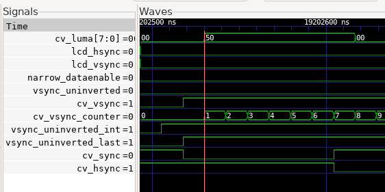
But first, we have to get the composite VSYNC signal fixed: The duration needs to be twice as long for 15KHz video as 31KHz video, so that it is still 5 raster lines long. To achieve this, I have implemented a counter that counts up while VSYNC is active, and then counts down again to zero when VSYNC is released. If this counter is non-zero, then the 15KHz VSYNC should be active. This works nicely to double the duration of VSYNC:

We can see that the composite video VSYNC (cv_vsync) signal holds for twice as long as the original VSYNC signal (vsync_uninverted_int). We can also see that the HSYNC pulses for the 15KHz video are happening only half the rate of those for the 31KHz video to the LCD/VGA display.
What is still not quite right, is that the VSYNC is happening half-way through a 15KHz raster line. Actually, that's not strictly a problem, as this is how interlace on composite video works, by having a half raster line. It's a really simple approach when you realise how it works: Whenever a CRT display thinks it is drawing rasters, it is very slowly advancing the vertical position down the screen. This is timed so that after 1 raster has been drawn, the display is now drawing 1 raster lower on the display. Interlaced rasters should appear half-way between normal rasters, so at the top of the display, you draw half a raster, to setup the offset. This also means that raster lines aren't strictly speaking horizontal lines, but are actually sloped slightly down towards the right. It would be interesting to try to observe and measure that effect on a larger CRT, where it should be visible.
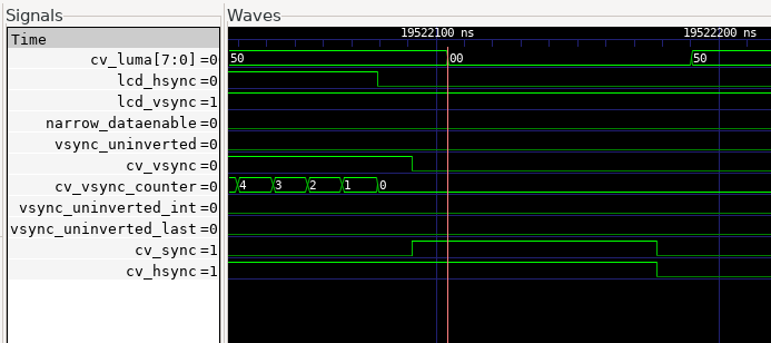
Anyway, I have made it selectable between odd and even frames now, and that fixes that problem, but I am seeing a 1-cycle glitch. This is because my VSYNC calculation is 1 cycle delayed compared with the HSYNC. So that should be fairly easy to fix. Except it turns out to not be that simple: The propagation of the HSYNC and VSYNC signals between 31KHz and 15KHz parts of the design are uneven. This means that VSYNC signal is rising 7 cycles before the HSYNC signal on the 15KHz side, as can be seen here:
i.e., we seee that cv_hsync drops 7 cycles after cv_vsync asserts. Since cv_sync is the XOR of those two, it results in this short glitch visible on the cv_sync signal, which then propagates to the cv_luma signal.
I guess I should just add in a 7 cycle delay to the cv_vsync signal. Because of how I set it up with the counter, I can just make it start when the counter gets to 7. That will make it start later. I will have to also check that it doesn't cause problems by making it finish earlier. If it does, I'll just come up with some little fiddle to deal with that, e.g., by creating an extra counter that caps at 7, and is added to the main VSYNC counter as it counts down, or something like that.
Actually the delay is 6, not 7 cycles, because I had put a one cycle delay on HSYNC when I thought that was the case. It being 6 cycles makes much more sense, as that is one pixel duration at 15KHz, and will be being caused by the logic that works out when to sample a 15KHz pixel value. This makes me happier, knowing how the difference in propagation time is being generated. Mysteries in VHDL code are usually a bad thing, i.e., will come back to bite you some time later, when it will be much harder to figure out the root cause.
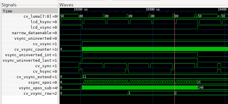
Okay, a bit more fiddling, and I now have the commencement of VSYNC in 15KHz video glitch-free:

Now, after adding the secondary counter to extend VSYNC by the same number of cycles as it was delayed by, we get the result we are after:

So now we have glitch-free 15KHz HSYNC and VSYNC signals. In theory, if I built a bitstream with this, the monitor should attempt to display an image. However, as we haven't yet converted the 31KHz pixel data to 15KHz, we would likely just get rubbish
Except, I just realised that during VBLANK, the sync pulses for 15KHz video are actually different: According to this, we need to put differing combinations of short and long sync pulses in each VBLANK raster for 15KHz. The pulses are also half-width, i.e., the same as for 31KHz. I think I'll add logic that works out which type of VBLANK raster it is: short, short, short long, long long or long short, and them make the means to generate each type, with the short and long pulse widths being automatically determined from the video stream. NTSC has similar requirements described here, which I'll deal with at some point. For now, I am focussing on getting PAL working, because I'm in Australia, a PAL-oriented country. NTSC will also require separate treatement when it comes to adding colour support.
Effectively we just need to know the sync sequence for the n-th raster of the VBLANK for both odd and even fields of a frame. I've got it partly working to do that now, where during the 31KHz VSYNC phase, it is putting the right things in:
But then it stops. This is because I should of course be using the 15KHz stretched version of the VSYNC signal... With that fixed, we now have a much healthier looking VBLANK sequence:

We can nicely see the 5 long sync followed by 5 short sync pulses, as required for a PAL odd field. What happens at the end of the even field, I haven't yet tested, because the the VCD file will be really big, possibly too big for my 2GB RAM drive where the logs are being written. But let's give it a try...

That looks pretty good, actually. The short/long sync pattern is shifted by half a raster-line as it should. The last SYNC pulse is a bit short, at 1.5usec instead of 2usec, though. The odd field has a similar problem. I should be able to fix both by just shortening each stage of the pulses, so that there is just enough time left at the end for a full 2usec pulse.
That fixed that, but now I am getting some glitches when VSYNC goes high. I think this will requires a bit of pragmatic bodging, until I squash them all. Which turned out to not be too hard. So finally, let's get back to the buffering of the pixel data, so that we can have a complete image!
First, I need to setup the two 1KB x 32 bit BRAMs. I could use a single 2KB one, but I don't think I have a VHDL model for that handy, so it will just be faster to setup two, and use the CS lines to select which one is being read/written at any point in time.
I have now hooked these buffers up, and got the scheduling right, so that they get written and read at the right time, so that the writing doesn't overwrite what is being read. Only just as it turns out, as the writing begins just after half way through the reading of a given buffer, and chases along the beam, only just failing to catch up in time. But that's ok. Here we can see the waveform of the write enable (_we) and read chip select (_cs) signals for the two buffers, and how this pattern repeats:

Hang on a minute. Something is not right here, because the 15KHz rasters should read for twice as long as the 31KHz rasters are written to, which means that the _we signals should only last half as long as the _cs signals, but they are the same length. I think this might actually be a red herring, as the write address gets to the end early, and stays constant after that. But I can clean that up, so that it is only active when required:

That's better. And in fact we can see that this buffering method can actually be reduced to a single buffer, because of this convenient aspect of the timing. That will actually greatly simplify things, as well as save a BRAM. It will also remove 1 raster line of delay in the composite output, which will also be good to fix.
But before I go optimising things, I want to make sure that it is actually operating as intended. And good thing I did, because it still looks like the 31KHz raster data is being written out.
Well, actually its half false-alarm, as I can see what the problem is: When the test pattern is selected, that isn't fed through the downscaler buffers. I'll fix that now. In the process, I also found and fixed some real problems where the composite image was being clipped by the data valid region of the 31KHz rasters, which would result in a vertical black bar in the composite output, if I hadn't fixed it. I also found a bug with the BRAM wrapper I was using not tri-stating the read bus when CS was low.
So with that all in order, now I can simplify things to use the single BRAM, and reduce the latency of the down conversion from 3 V400 rasters to just 1. That is, our composite conversion has a latency of only 32 usec, which I think is pretty acceptable :)
Removing the BRAM seems to have gone without problem.
So this finally menas that we are ready to try to build a bitstream that produces a composite luma on the expansion board. Initially it will just be a test pattern bitstream, not the actual MEGA65. This is because the test pattern bitstreams are much faster to biuld -- about 10 minutes instead of an hour -- which makes development more convenient.
Ok, so first bitstream generated, and I can see at least some sort of signal that seems to have HSYNC and VSYNC structure to it. Sorry about the crappy images from my phone camera. I still have to do something about that, and the lighting here at night is not great, either:


In the top one we can see something like a VSYNC structure, while the bottom shows several HSYNC pulses.
However I am not seeing any of the test pattern luma signal overlaid on this, which is odd. The test pattern is overlaid in pixel_driver.vhdl, and in this test bitstream it hard wired on, which I can confirm because it comes through on the HDMI monitor I have connected to the MEGA65. But its late now, so I will have to investigate this problem tomorrow.
It's another day, and hopefully I'll figure out the cause of the lack of pixel data in the luma signal. It looks completely flat. First step, I'll modify the output so that the read address of the raster buffer is output on the green channel. This should super-impose a sawtooth pattern on the luma signal. If it shows up, then I'll assume that the problem is in writing to the raster buffer. If it doesn't show up, then I'll assume that the problem is further down the pipeline. Either way, I'll have narrowed down the hiding places for the bug.
Okay, so the sawtooth is visible:
It's a bit non-linear and steppy, but I'll investigate that later. First step is to figure out what is going wrong with the pixel data.
Next I'll check whether writing to the raster buffer seems to be working. I'll keep the existing sawtooth on the green channel as above, and put the write address of the raster buffer on the blue channel, which will have lower amplitude than the green channel, and will also have a different slope and phase than the other, so I should be able to see them both superimposed without problem. Again, if I do see it, it will tell me that the raster buffer writing and reading is working fine, and thus that the problem must lie in grabbing the test pattern pixels, and if it doesn't show up, then the problem is in the raster buffer writing. That is, I'm again splitting the remaining bug hiding territory.
And no pixel data shows. So it seems most likely then, that the writing to the raster buffer is the problem. A bit further digging, and it seems that raster15khz_waddr is not being updated, but just stays at zero.
Now, the signals that can be influencing this are:
1. new_raster -- when it is 1, then waddr is clamped to zero
2. raster15khz_waddr_inc -- when it is 1, then waddr will be incremented
3. narrow_dataenable_internal -- when it is 1, then raster15khz_waddr_inc can be asserted.
4. hsync_uninverted_int -- when it is 1, waddr is clamped to zero.
narrow_dataenable_internal is probably fine, because otherwise the HDMI image would not be visible. So let's look at the other 3. I'll again just try superimposing them onto the luma signal.
hysnc_uninverted_int is confirmed fine through my testing. So that just leaves new_raster and raster15khz_waddr_inc as prime suspects. Either or both might be working, but not visible in my test, because they are signals that are 1 cycle in duration, and thus might not get picked up by the once per 6 cycles sampling for the luma. To help here, I will add signals that toggle whenever those others are modified, so that I can still see if they are changing. First I'll check with new_raster. new_raster is also ok.
So that leaves raster15khz_waddr_inc as the prime suspect. This is gated by buffering_31khz, which is working. Thus things are looking very much like raster15khz_waddr_inc isn't being asserted... Except that it seems to be.
Hmm... and even raster15khz_waddr seems to be working now. Weird, as I am fairly sure before that it wasn't. Anyway, I've moved on and checked that sensible looking data is being fed to the _wdata signal as well, which it is.
So if waddr and wdata are good, is the write-enable signal being asserted? Also the select line for the read side? Write-enable does indeed get set at the right time. the select line for reading looks fine, too, although it can in fact be hard-wired on, in case it is somehow the root cause... and that worked.
So the luma signal is now showing rasters of sensible looking pixels. I can also see the HSYNC and VSYNC pulses. However, between the sync pulses during the VBLANK period, the signal is not returning to the 30% point, but rather is reaching 100%. That was fairly easy to fix, by enforcing black level during VSYNC.
There is one more anomaly that would be good to fix, though: Whatever was in the last raster line of a field (ie single vertical retrace, which might be a whole frame if not using interlace, or is half a frame if using interlace), is repeated during the entire VBLANK period. This should be corrected for a variety of reasons. One, its just causing misleading information in the frame. Two, some TVs calibrate their black level based on what is happening during this period. Three, teletext and closed caption text is normally transmitted on the VBLANK lines. We don't want to accidentally trigger this. I'd also like to potentially implement at least closed captioning at some point, just for fun. But not yet.
So let's just fix the VBLANK rasters so that we prevent the retransmission of the last raster. A simple approach would be to have a signal that notes if a valid data pixel has been seen in the recent past. Another would be to count raster lines, and mask based on that. Time since last pixel is probably the simplest and most robust for use with PAL and NTSC.
The time since last pixel method works fairly well, but does result in some glitching in the raster immediately following the start of VBLANK, as the first part of the raster will still be drawn. Similarly, the first raster line after VBLANK will suddenly start part way through the raster. Both of these issues are quite livable.
Anyway, with all of that, we get a nice VBLANK arrangement looking something like this:

Here we can see, from left to right, a few jaggedly lines of pixel data, then a single raster with a white line, near the little arrow at the top. As white is bright, it has the highest voltage, thus that raster just has a signal at the top. The little spikes below are the SYNC pulses. Then to the right of that, we see some black rasters at the start of VBLANK, followed by the VSYNC pulses that are mostly 0V, but with short spikes up to black level. Then after those we have black raster lines until the start of the next frame, which begins with the white raster line on the right edge of the capture.
(As you can also see, I also managed to dig out a better camera, too :)
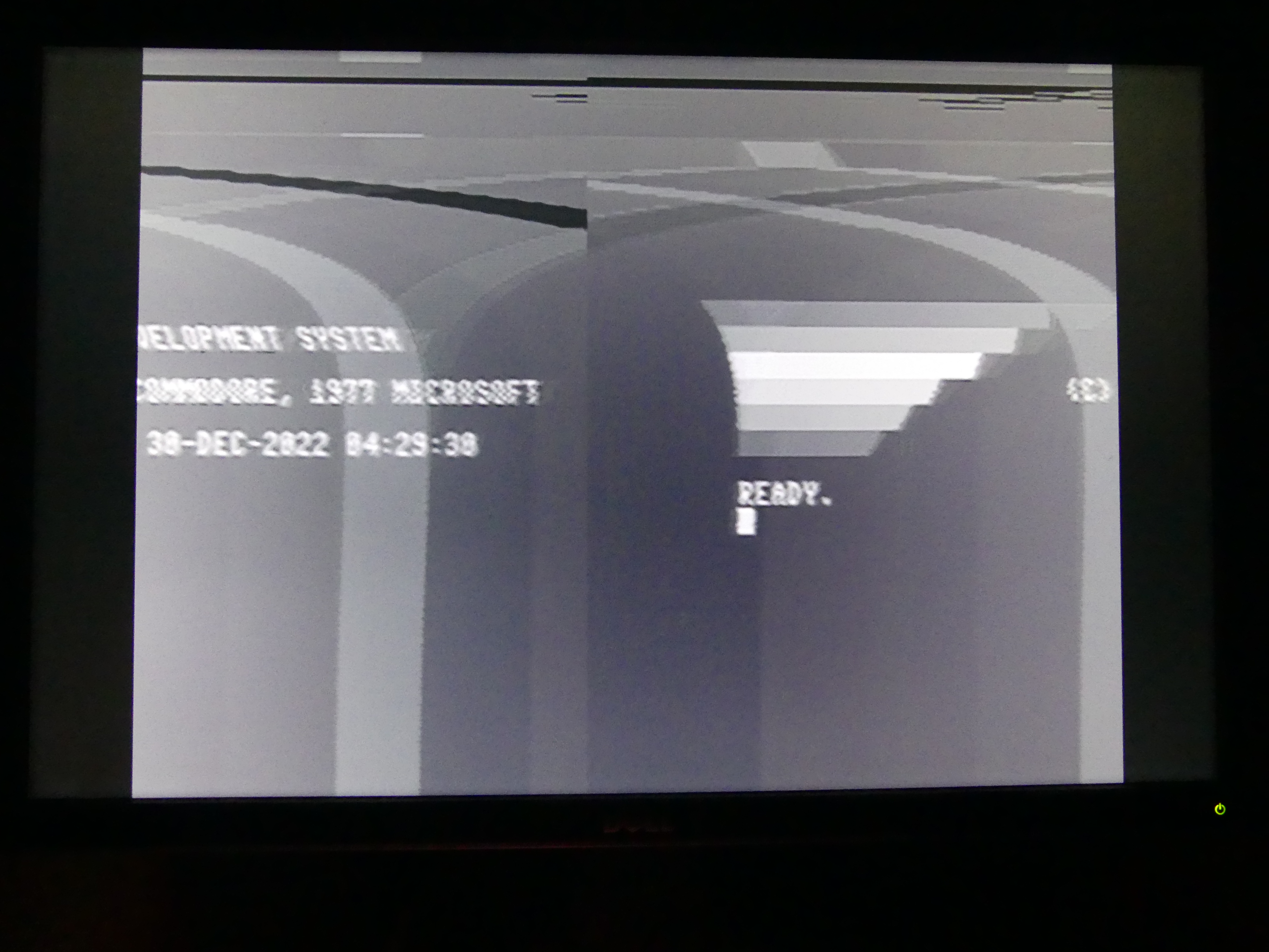
In short, I think we have a perfectly valid composite monochrome signal. Now to find a monitor to feed it into... and this is what I saw when I selected the composite input:

Yay! All that methodical drudgery to make sure the signal was correct paid off -- I got a working and stable composite image first go :)
Then I found the "fill to aspect ratio control":
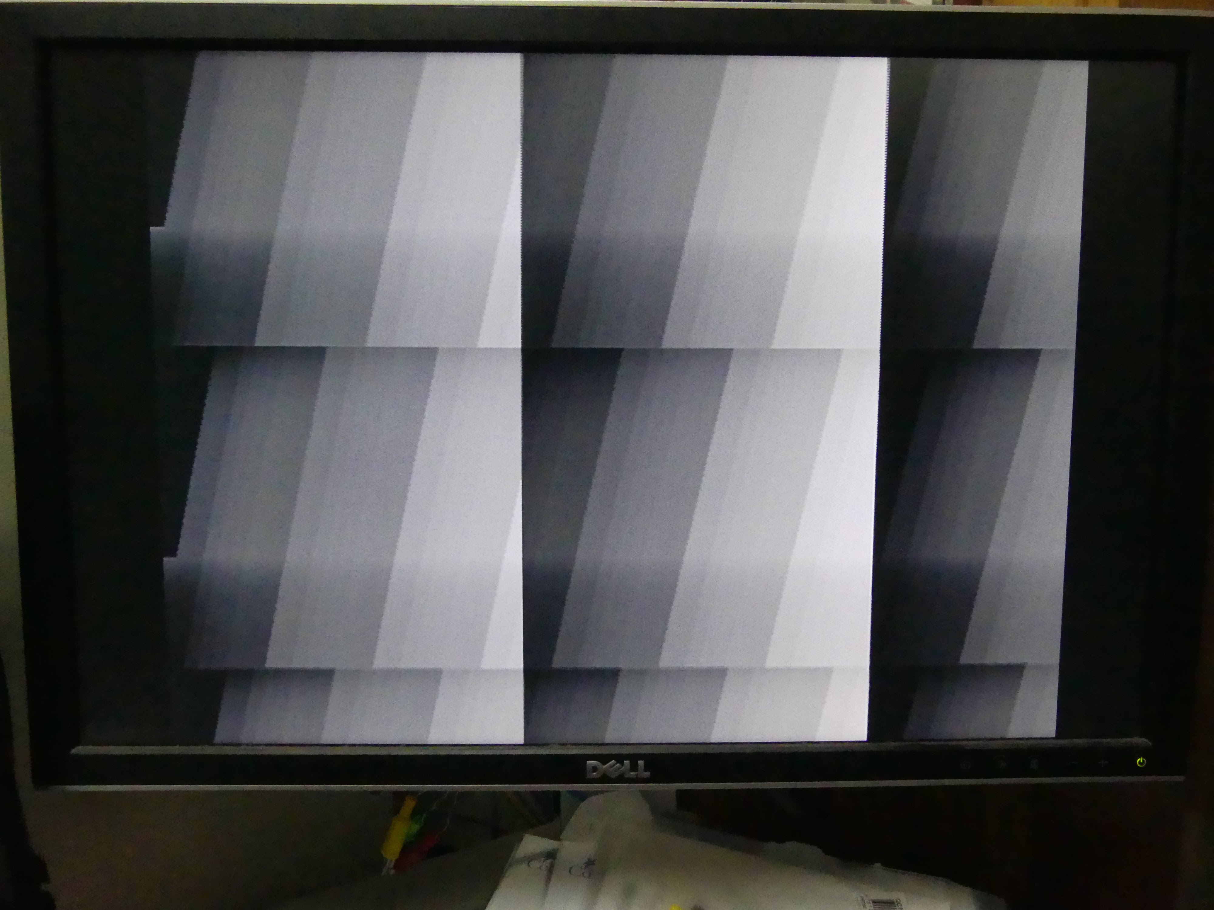
Much nicer :)
Looking at it, I can see a few things:
1. My effort to increase the bit depth of my 4-bit resistor DACs by oversampling 10x seems to have worked, because I can make out more than 16 levels of grey -- and this image doesn't even go to full intensity with white. So that's a nice win.
2. Looking closer, I think I have the interlace the wrong way around. You can see a jagged edge on the sloped bars, and a feint detached line just above the short horizontal transition on the left:

That will be easy to fix, and also means that I have correctly implemented interlace. Another nice win :)
For reference, this is what is on the HDMI display:

Back to the composite output, the lack of linearity in the shading reflects what I was seeing on the oscilloscope, that something is messed up with the DAC. I'll look at that shortly, but first, to fix the interlace bug.
Ok, the interlace bug fix is synthesising, so in the meantime I am having a think about the non-linearity in the DAC. Actually, I just noticed something else: When the image starts from the very left, it is causing those whole raster lines to darken. This means that I have the video starting a little too early -- or similarly, that I am trying to display too many pixels on each raster. Either way, the monitor thinks that part of the raster is during what should be HBLANK.
Fixing this will be a bit trickier, because we are sending 720 horizontal pixels, to match the MEGA65's horizontal resolution. But at the 13.5MHz pixel clock for the composite video mode, this is probably taking more of the raster line than it should. Trimming pixels on the left will reduce the side-border width, however, which is not ideal, especially since many TVs will likely cut some of the raster off, anyway. The ideal solution would be to use a 720 / 640 = 13.5Mhz x 9/8 = 15.1875 MHz pixel clock -- but we can't really add any more crazy clock frequencies in, or we will have more problems. Or in the least, a lot of work, because I would have to implement some kind of horizontal sub-sampler, which could also be done at 13.5MHz to go through the raster faster.
The simplest method remains just trimming some pixels off the left (and possibly right) side of the image. I'll start with that, and we will worry about improving it from there. It might only need a few pixels trimmed to fix the problem.
16 pixels was enough to fix it, and in fact 8 is enough, too. I'm now about to try 4. Here is how it looks with only 8 trimmed. You can see the reduction in brightness part way down the pattern has disappeared:

It's entirely possible it will turn out that only 1 or 2 pixels is required, if I have erroneously slightly advanced the start of the active part of the raster. That would be a nice outcome. Once we have it working on the MEGA65 core, I will be able to check how much is being trimmed from each side, and whether any further adjustments are required.
Ok, so 4 pixels is enough. Trying 2. If that's fine, I'll leave it at that for now, and start trying to synthesise a MEGA65 core with mono composite output. It will be interesting to see how PAL and NTSC switching goes with that -- in theory it should just work, but I have only tested the PAL image with my test bitstream so far.
Trimming just 2 pixels is indeed enough, so onto the MEGA65 core synthesis.
First go at building a MEGA65 core with the monochrome composite output in resulted in a dud: I had accidentally tied luma and chroma together, and as chroma currently is just tied to ground, there wasn't any signal. So its building again now, with that fixed. But once again, the day has run out, so we will have to wait until the morning to see if I have been successful.
Hmmm..., well, I have a picture now, but it has some significant problems: Essentially the VSYNC seems to not be working, and the HSYNC seems to be out by half a raster line or so.

Just for fun, I tried switching to NTSC, and that's less bad, in that it has working VSYNC, but HSYNC still seems to be out by half a line, and there is some serious problems with the capture of the HSYNC in the upper half of the display, causing the most interesting (but unhelpful) effect:
What can't be seen so easily in these shots because of the relatively short exposure time, is that for NTSC, it is trying to switch between two different horizontal positions. I suspect that the half-rasters for the interlace control might be messing things up.
The big mystery, though, is how this is all happening, when the test pattern was rock solid. Enabling test pattern mode in the MEGA65 via $D066 bit 7 shows these same problems, so there must be something different about the video signal being produced by the MEGA65 core.
The most likely suspect I can think of, is that the genlock related logic is causing the frames to be a bit long or a bit short, and that is then confusing things... except it seems that I haven't actually plumbed that through, so it can't be the problem.
Hmm, using the oscilloscope, I can still see the HSYNC and VSYNC pulses, so I don't think that that is the problem. The amplitude of my composite signal might be too large, but then its no different to with the test bitstream. In fact, that's the whole point: When the test pattern is enabled, there is obstensibly no difference between the generation of the signals. Yet clearly something is different. Perhaps there is more jitter or more high frequency interference on the video signal from the FPGA, since it is doing a lot more stuff when the full core is running, compared with my test bitstreams.
Ah, interesting, I just tried one of the test bitstreams, and it was doing the same thing. Turn monitor off, turn monitor on, and its back to being rock-solid.And back to the MEGA65 bitstream, and I now have something resembling a stable display. It still has several problems, though, as you can see here:

There are three problems I need to deal with:
1. In the upper part of the display, there is an oscillation in horizontal position, that clears up by about 1/2 way down the display. This also happens with the test bitstreams, so I can at least investigate that a bit faster.
2. There is vertical banding coming from somewhere. It doesn't appear when test pattern mode is enabled with the MEGA65 core, so that's a bit of a mystery.
3. As I discussed earlier, my suspicion is correct that the monitor is only displaying the first ~640 or so pixels of the 720 wide: I need to speed up the playback of the 720 pixels to make them all fit in the correct active part. If I do that, and add a "front porch", it is possible that problem 1 will disappear.
So that's probably where I should start.
The active part should apparently be 52usec long. We have a 4usec HSYNC and 8usec back porch = 12 usec, leaving 64 - 12 = 52 usec. So in theory we are allowed to use the whole remaining raster, but then there is no front porch. Elsewhere I read that the front porch should be 1.65usec, which makes more sense. On my monitor the last four or five 80-column chars are not visible, corresponding to 32 -- 40 pixels. The side border is a similar width, making for close to 80 pixels in total -- i.e., the difference between 720 and 640, thus confirming my suspicions here.
To fix that, we need to reduce the active part of the raster from 52 usec to 52 * 640 / 720 = 46.2 usec. That would leave a ~5.8 usec front porch, which should be plenty.
Now the real question is how to do this, without messing up the horizontal resolution. As I mentioned earlier, ideally I would just use a faster clock to play back the buffered data. But I can't just add any more arbitrary clocks.
Probably the easiest way will be to vary the number of 27MHz cycles between pixels. 720/640 = 9/8. So I just need to increase the playback rate by that fraction. Currently I advance a pixel every 6 clock ticks at 81 MHz to get the exact 13.5MHz pixel clock. Speeding that up by 9/8 means it should be 5 1/3 cycles instead. So I can switch to 5, and then every 3rd pixel stretch it to 6, and it will work out. Hopefully the pixel widths varying by 20% won't be visually noticeable. But there is only one way to find out!

We now have all 720 horizontal pixels display, and the 20% jitter in their widths is not immediately noticeable, which is good.
But there are two big issues still visible here:
1. Those weird vertical bars, and it probably can't quite be seen in this image, but there is actually some fainter vertical banding going on in there, too.
2. The two fields of the interlaced display are diverged by a fair amount at the top of each frame, and only line up in the lower third or so of the display. I'm fairly sure that the root cause for this is that I am not doing something quite right with the vertical sync signalling.
As a first test for the horizontal position stuff, I tried disabling interlace, and just using "fake progressive", like the C64 did. But that results in even worse divergence, with it initially syncing to a half-raster horizontal offset. This again points to some problem with the vertical sync signalling.
While I was doing that, I completely forgot that the VIC-III actually has register bits in $D031 to select interlaced video, as well as mono composite output, i.e., disabling any PAL/NTSC colour signalling. So I have hooked those up into the pixel driver. The interlace bit might end up needing an override, as some existing software that uses V400 doesn't set it, which means that the composite output would not display the alternate rasters, but rather the same 200 vertical lines all the time.
Reading Video Demystified, I can see where part of my problem is coming from: The rasters really are offset by half a raster on each successive frame, which explains why the monitor is trying to lock onto a half-shifted line. This means that the HSYNC and everything have to be shifted half a raster early. It also means that we are supposed to have a trailing half raster on those fields that are shifted by half a raster. That should actually be fairly easy to do, as it will occur quite naturally.
Hmmm... Investigating, it looks like we should already be switching the composite HSYNC by half a raster on alternate frames. But it isn't happening. So that's the first thing to investigate. The field_is_odd signal is being generated correctly, and is being passed into the frame_generator units. Those are also selecting the alternate Y lines based on that. That then directly sets the raster X position for the composite lines, which should then result in the correct positioning of the HSYNC pulse for the composite rasters -- but isn't. Or if it is, its then being magically overridden and ignored.
Ah, one minor bug to fix: When I shifted the pixels to being 5 1/3 ticks wide, I didn't update the delay from HSYNC to start of active area, so it will be a little early. I'll fix that while I'm here, but it shouldn't be affecting the real problem we are chasing here.
Okay, for the HSYNC problem, it looks like I got too clever pants: Because the 27MHz ED TV native mode of the VIC-IV uses an odd number of rasters, 625, this means that if we don't correct for which SD TV 13.5MHz field we are displaying, that the 1/2 raster shift will occur naturally. But if we try to make it do it, then it will cancel out, and not happen -- which is exactly what is happening.
Just to add to the fun: This problem with the half raster line toggle is PAL specific -- NTSC does not need it, and when I switch the display to NTSC, indeed, it looks rock solid, although those vertical bars are still visible, but fainter (also I didn't update the display geometry after switching, so the display is shifted down somewhat):

Enabling interlace for NTSC messes things up, though, because it tries to put the half-raster offset in, which I believe is not required for NTSC. I'll investigate that later. Interestingly I am seeing the same vertical banding as with PAL, but the vertical bars through the background are quite a lot fainter. Again, something to investigate after I have PAL display stable.
The best way to do this is to use simulation, so that I can look at the perfect signals being generated to look for the correct structure -- or lack thereof. Unfortunately, it takes about 6 minutes to simulate 2 fields = 1 frame in my VHDL test bed, which is a bit disruptively slow.
To solve this, I am adding a debug feature to the pixel_driver module that allows shortening the frames during simulation (but not synthesis), so that the simulation time can be greatly reduced. It was around 6 minutes, and now I have it down just under a minute, and could probably trim it further if necessary, but this will do for now.
That certainly saved a lot of time, and it didn't take too much longer to get the PAL VSYNC trains looking like they should. Or at least, I think they are right now. While my head is in this particular bucket, I'll also work on getting the NTSC VSYNC trains right, which have slightly different timing compared with PAL.
I am now trying to get the VSYNC trains exactly right for NTSC, and am pulling my hair out a bit. I think one of the root causes is that I used the convention of the HSYNC pulse being late in the raster instead of start of the raster on the MEGA65, which turns out to not be the convention. This means that VSYNC seems to start just after an HSYNC pulse, which complicates other aspects of the logic. It might be causing issues for the PAL as well -- which I'll check when get get back to that.
Meanwhile, my problem is that the HSYNC occurring just before VSYNC asserts means that I have a full-width HSYNC just before the VSYNC train, instead of a half-width one. The pragmatic solution is just to fake the rest of the raster line, and then do the proper thin HSYNCs after that.
Several hours of mucking about to get this sorted, and I think I have NTSC more or less right now. The image is stable in the horizontal direction. The only remaining issue is that I had an out-by-one vertically with the interlace that was causing problems when interlace mode was enable. With it disabled, it looks rock-solid. I also found the stupid error causing the vertical banding (old debug code writing stuff into the blue channel), and the cause of the disappearing test pattern in NTSC. PAL is still playing up, but might similarly have a vertial out-by-one that is confusing things. I'll find out after I have a nap.
Okay, several more hours of incrementally spotting and fixing timing errors, I now have PAL and NTSC working in both interlaced and fake progressive mode.
One interesting thing, is that a minor timing tweak I had to do for 50Hz digital output I have been able to remove when interlace is enabled, because interlaced PAL video actually has 1/2 a raster line more than progressive. This means that if interlaced PAL is enabled, the rasters are now back to being 864 ticks instead of the 863 I was using to match C64 timing. It also means that the MEGA65 set to 1MHz and PAL will by about 0.2% faster if fake progressive is selected instead of interlace mode, because of the selective application of this timing fix.
Meanwhile here is a quick example of the effectiveness of interlace mode. This is on this old DELL LCD monitor, so it is digitally persisting the alternate fields, allowing it to remove all flicker. I started with the MEGA65's READY prompt, and just set the V400 bit (bit 3 of $D031). Without interlace, it is only displaying every other raster, making it look pretty bad:

Now if we turn interlace on, by setting bit zero of $D031 (this means that, like on the C65, V400 and interlace are independently selectable):

Note that even though it will flicker on a CRT, it will flicker like an Amiga, not like a C64 trying to do interlace, because the C64 uses fake progressive, which doesn't do the vertical interleaving of the lines, as I mentioned earlier.
So now onto getting colour working!
I have already prepared a 256-entry SIN table. We are clocking out pixels at 81MHz, and we need to produce colour bursts at two very specific frequencies for PAL and NTSC respectively:
PAL: 4.43361875 MHz
NTSC: 3.57561149 MHz
These have to be synthesised very accurately, so that the magic of the separation of the colour (chroma) and the brightness (luma) signals from one another can happen effectively in the TV or monitor. These frequencies weren't chosen by their creators randomly, but rather were specially designed so that harmonics from them neatly (mostly) stay away from those of the luma signal.
Our 81MHz video clock is 18.269500507 the PAL colour carrier, and 22.650278938 the NTSC colour frequency. This means that each 81MHz cycle, we need to advance by 360 / 18.269500507 = 19.704972222 degrees (PAL) or 360 / 15.893844 degrees (NTSC). Of course we are working in binary, so we will use a system where the circle has 256 "hexadegrees". In this system, the required advance is:
PAL: $E.032E43BA hexadegrees
NTSC: $B.4D62D0F8 hexadegrees
As we can see, the fractional part just carries off into the sunset, rather than ending nicely after a couple of digits. 32 bits of precision is more than enough, as the FPGA's clock is unlikely to be more accurate than about 10 parts per billion, anyway. That will get us well within 1Hz accuracy, which is plenty.
To count these accurately, we will need to have a whole and fractional part of the current signal phase in hexadegrees, and add the appropriate quantity to each every 81MHz cycle. We have to be a bit careful, because adding a 32bit value at 81MHz has the risk of having poor timing, and we probably in fact need a 40 bit value to have 32-bit fractional part plus 8 bit whole part (we don't care how many cycles).
The colour burst signal is the first part that we will implement. This consists of 9 +/- 1 full cycles of the colour burst signal during the horizontal retrace, a "short time" after the end of the HSYNC pulse. We will just time 2usec after the end of the HSYNC pulse, and put it there. For NTSC, the amplitude should be 40/140ths = ~29% of the full range of the video signal. As our sine table is based on a full amplitude of 255, this means that we have to scale it down to 73/255ths. PAL uses a slightly higher amplitude, which boils down to 78/255ths.
For NTSC, the initial phase of the colour burst signal varies for odd and even lines when interlacing, with the phase changing once every two fields, i.e., full frame. This can be implemented by inverting the phase after every odd field, using the naming of the fields that I have in the pixel_driver. Also, the colour burst phase has to be set to exactly 0 or 180 degrees ($00 or $80 hexadegrees) at the start of the colour burst on each line. For non-interlaced NTSC, the colour burst phase remains at zero degrees at the start of each burst, i.e., it does not alternate every frame.
For PAL, we also have to enable or disable the colour burst on the last and first whole raster of each field, as described in Figure 8.16a and 8.16b of Demystifying Video. I'll come back to that later. Otherwise, instead of using a 0 or 180 degree initial phase, PAL uses 135 or 135 + 90 = 225 degrees = $60 or $A0 hexadegrees, and this alternates every line within a field, as it does with NTSC.
For fake-progressive PAL, a fixed pattern is used, rather than changing each field.
That should be enough information for me to implement the colour burst signals. After that, I will have to implement the actual colour information and modulation onto the signal.
In the process of looking at this, I realised the cause of a minor issue I noticed earlier this morning: The NTSC luma was noticeably dimmer than PAL. NTSC uses a black level which is somewhat above the sync level, which I wasn't taking into account. I'm also suspicious that I had some error in the luma calculation that was causing the non-linear banding. Finally, these calculations needed to be reworked, anyway, to leave enough head-room for the modulated colour information. So I had to recalculate them, anyway. I'll generate a test bitstream with those tables, and it will be interesting to see if in addition to having more consistent brightness between PAL and NTSC, whether it has fixed the non-linear banding.
To help with testing this, and the colour representation in general, I have added grey scale and pure RGB bars to the test pattern. Eventually I should also add colour saturation bars as well, but step by step.
This is what the test pattern looks like with digital video output:


The non-linearity is still there, so it wasn't an error in the luma calculation. Oh well. But I have fixed the NTSC darkness issue -- PAL and NTSC now have very similar brightness.
And since this post is already about five miles long, I'm going to stop at this point, and start a new post, where I focus on actually adding the colour information, now that I have everything in place for it.
No comments:
Post a Comment