Sunday, 31 March 2019

Name Plates for the MEGA65 pre-production units have arrived!

So, the next fun part of the pre-production run for the MEGA65 computers has arrived - the name plates!  We thought a lot about how we would like these to look, and are generally quite happy with the result. We hope that you will all like them, too:


These are not stickers, but are 0.5mm thick aluminium plates, with nice rounded corners, and 3M adhesive to hold them in place.  Thee writing on the top is actually raised up as well, as we really wanted something that is simply a delight to behold.  We were very pleased that they fit perfectly in the slots on the SLA 3D printed cases we produced a while back, and look very much forward to fit-testing them on the new pre-production cases when those arrive :)


Friday, 29 March 2019

MEGAphone First Prototype PCB remediation and first light

We began by testing that the voltage levels on the board were correct. This is important, because the MEGAphone is designed to run on battery, and thus has step-up/step-down regulators to provide the various power supplies.

I say the various power supplies, because the MEGA65 has six switchable power supplies, so that you can selectively power down sub-systems based on the security level of what you are doing. For example, you can power down the bluetooth and wifi, so that nothing can attack you that way. Similarly, you can power down the microphones, so that there is no way at all of someone listening in on you from afar.  The cellular modems and LoRa radios can also be separately powered down.

So, anyway, this means we have 7 voltage regulators in total, as the FPGA also has its own power supply, but no switch to control it -- that is instead done via soft control from the FPGA, via a power control line.

In our initial testing, we found that the rail for the FPGA board was 6.45V instead of 3.3V.  Fortunately I had the presence of mind to not plug it in first time.  We eventually tracked the problem down to a resistor that had come loose during the hand-soldering process. This won't be an issue  in production, because all assembly will be fully automated.

In the process of trying to fix it, I did accidentally lift one of the pads of the resistor from the board.  Needless to say, I wasn't real pleased. I was able to bodge it up with a couple of fly wires, and some lovely full-size resistors to create the correct overall resistance, as we didn't have the exact value resistor on hand.  Bodge is indeed the correct word here. I meant to add a photo, but forgot to upload it.


With that solved, it was time to make sure we can program the FPGA board.  This took a little fiddling, as I was trying it not-plugged-into the MEGAphone board, and it turns out you have to set a dip-switch setting for the little programming board to get power from the USB port.  With that figured out, I was able to fairly quickly get a working blinking-LED bitstream running.

Then from there, reset the dipswitch, it was time to insert into the MEGAphone board, and program the FPGA.  Success first time: blinking LED on the FPGA board.

Ok.  So, from here it gets a bit more interesting, as we need to map the FPGA pins to the TE0725 FPGA module pins, and from there to the MEGAphone schematic.  The TE0725 is designed to be rotateable, in that the connectors are symmetric, allowing us to slecxt the preferred orientation of the board.  I have opted to have it oriented so that the programming cable can stick out the side.

Now for a little detective work to match up the pin numbers. This would be a whole lot easier, if we had a directly connected LED on the MEGAphone board, but we don't.

We do have some fairly easily probable lines to the WiFi adapter, though. So that might be the best way to work out which end of the connectors is pin 1, and match everything through.  Once we have the pin order more or less under control, I can try synthesising the entire MEGA65 design, with the VGA output enabled.  That will be a happy moment, to see the MEGA65 boot screen.

So the WiFi UART lines are on connector B pins 44 and 48, according to the MEGAphone PCB schematic. According to the TE0725 schematic, this should be FPGA pins L1 and L4, assuming the orientations are around the right way.  So let's try to make them toggle between high and low. To tell them apart, I will make them toggle at different rates: 0.5Hz for L1 = WIFIRX, and 2.5Hz for L4 = WIFITX.

Fortunately synthesising such a simple design doesn't take too long, but it does still somewhat inexplicably take around 5 minutes.  It feels like I could build the circuit by hand faster!

Ok. Bitstream synthesised.  Now we have the extra fun that the power control circuitry on the MEGAphone has to be reckoned with: There is a line connected to the FPGA board that allows the power rail to the FPGA to be shutdown.  To turn it on, you have to press the power button, or wait for an interrupt from one of the support chips.  Of course, the power on button is on the front of the board, which is on the back from the perspective of how I have it sitting on the desk.

In trying to flip the board over to get to the button pads, I discovered that the power supply GND line had come loose. Fixed that, and I had power again.  Excellent!

While waiting for synthesis, one other annoying thing I have at the moment, is that the fpgajtag program I use for conveniently programming the FPGA from the command line doesn't seem to work with this particular FPGA JTAG adapter. Oddly, the one I have at home does work in this mode. I don't really have any idea why as yet.

Okay, the new bitstream is finally running, and after fighting with a bad ground on the oscilloscope probe, I can find the signal on pin 48, but on the opposite side and end as expected - so our coordinates are rotated.  No problem, find the pins from the schematic, and try again.

So pin 48, which is one in from the end should become pin 3, so that it is on the opposite side, one pin from the end.  Pin 44 should then become pin 7.  And of course, we have to switch between the two connectors.  So WIFIRX should be L15, and WIFITX should be L23.  But now that we know where L1 and L4 are, we can check continuity on the connector to the WIFI port, and work out that it should actually be pins 4 and 8 instead of 3 and 7 to be on the correct side.

Ok. Now another bit of fun, is that the labels for the header pins on the TE0725 FPGA board aren't actually FPGA pins. So a bit of searching and hair-pulling was required. Actually, quite a bit of both.  But in the end I made a chart that lists the pin assignments:


Then it was time to help some students in another lab, but as luck would have it, there were only a few, so I had some more time to work on this.  So everything went on the trolley, and came down with me.  This is not exactly the intention of a portable MEGA65 to require a trolley, however ;)


But as you can see, I managed to get the VGA output, and also the UART monitor interface correctly connected.  However, the SD card doesn't yet work, so booting to BASIC requires the use of the monitor_load utility to load everything.  We can see in the shot below that the hypervisor is not having much luck finding an SD card:


This monitor also wasn't that thrilled about the HSYNC timing, which I will deal with later.  Here is another shot of the screen after booting to BASIC:


MEGAphone First Prototype PCB assembly complete(ish)

So, I am back in Australia now, and the workshop folks have ordered and received the main missing parts, and have assembled the board. So let's start by taking a look at it.

First, the front: Nothing too much to see here, except that of course we don't yet have the joystick direction and buttons populated, nor the speaker, volume thumb-wheels or system buttons at the bottom:


Then the rear side, where there is a lot more happening:
 First, we have the yellow insulating tape applied below where the cellular modems will fit. Let's continue the tour, by going through the photos where I have noted problems or missing components.

 Here we can see a couple of ICs are mmissing, which we have noted.  The big one with lots of space between the pins is the ADC for the headphone microphone.  The little 8-pin job near the middle of the image, I don't specifically recall what it is, just that it isn't important for initial testing.

Here we can see the power supply for the FPGA and two other sub-systems near the middle (small black chip with cluster of little components around them).  One of those had a loose resistor, which we had to fix. Also, on the upper left, we can see an 8-pin header. This should be female, and is for the ESP8266 Wi-Fi module.
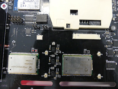
Immediately above that is the bluetooth chipset, which is quite flexible, and should allow the MEGAphone to use headsets, as well as to act as a set of bluetooth speakers, if you ever had the need.  To the right of that the big white thing is a full sized SIM/SmartCard reader.  I've got plans for that, that I will write about in another post.  Then below that is the wide connector for the LCD panel, and the little white thing somewhat to the left of that is the connector for the touch screen digitiser. We already know that the LCD connector needs too be about 1cm to the right, and that both should be a couple mm lower down on the board. You can also see the pair of LoRa radios, which give tri-band UHF functionality at 434MHz, 868MHz and 915MHz. Those are there because I like resilient telecommunications solutions. It also means it should be possible to play multiplayer games upto several km distance between players :)

 I mentioned the problem with the LCD connector placement, you can see that here in a more practical way:


 Also, it turns out the SIM card slots we got are too tall to sit beneath the modem slots, so we will need to do something about that. The big green thing to the right is the battery connector.


 And we accidentally ordered the wrong gender for the joystick port. So no two-player action for us until we replace it, or make a gender-changer:


Now, back to the LCD screen, we spotted another issue: the 5mm LEDs don't leave enough space for the digitiser to sit flat:

 You can see the problem better here: There is about 1/2 an LED too little space:
 Fortunately, if we switch to 3mm LEDs, we save 2 x ( 5 - 3 ) = 2 x 2 mm, which is enough.  Also, nice red LEDs will look better, anyway. So let's do a fit test with one of the unpopulated boards:


Looks like it should work :)

Okay, so that's a quick walk through the hardware.  Now to try to get it to power up and do something.

MEGAphone First Prototype PCB assembly underway

As many of you know, we have a side-project of the MEGA65 to make a hand-held/phone version of the MEGA65.  This project works using project students at the University, and gives them the opportunity to be engaged in the project, without us risking our critical path by depending on student labour, which due to a variety of factors can be complicated.

So what we have here, is the re-worked R1 PCB layout for the MEGAphone hand-held, based on work by some students last year, and then a number of problems fixed and final layout by our engineering workshop folks.

I'm currently in Germany as I write this, so I have only the photos that the workshop folks have taken during the assembly process:


As you can see, the assembly is already well underway, with lots of the surface mount components already in place.  Otherwise, clock-wise from top left we have the VGA connector (for testing and connecting to projectors etc), the Bluetooth module, full-size smart-card reader, which can also be re-purposed to support full-size SIM cards), then a bunch of power components and the headphone jack.

Then down the right side we have the dual sim cards that sit under one of the two cellular modem / alternate radio slots.  Bottom right, we have the joystick port, for if you want to play two-player while underway, or for when the D-PAD joystick (which is on the opposite side) isn't enough.

Then bottom left we have the SD card slot and the dual headers for the FPGA module from Trenz Electronics.

Otherwise in the middle we have the two unpopulated LoRa radio chips for mesh networking experiments, and the white connectors for the touch screen display and sense cables, and the slots cut in the board for those cables to go through.

The current hope is that the board will be finished being populated by the middle of March or so -- very exciting, and just in time to bring in more students to work on the project for the new academic year (which begins in March in the Southern Hemisphere).

Tuesday, 12 March 2019

Speeding up formatting and freezing with multi-sector SD card writes

The MEGA65 format utility can take a terribly long time to run, making you feel rather much more like you are in the 1980s than you might like to, especially when formatting a large capacity 64GB SDXC card or similar.   This is because until now we have not supported multi-sector writes to the SD card.  As a result, the SD card controller must read an entire flash block (often 64KB or larger), modify the 512 byte sector we have written, erase the entire 64KB block in the flash, and then put the new data back down.  The end result is that it is about 10x slower or worse than it could be.

This problem also affects the freeze menu that has to save ~512KB of data every time you freeze.  Because the SD cards are smart internally, they tend to ignore writes with unchanged data, but even then, you have the penalty of the ~64KB block read internally in the card.  Thus freezing a problem that had very different memory contents than the last frozen program could take a number of seconds.  This was quite annoying when all you might want to do in the freeze menu is toggle between PAL and NTSC, for example.

Thus I figured the time had come to attack the root cause of these problems and implement multi-sector writes on the SD card.  But first I had to figure out exactly how they work. This was not as easy as it sounded, as there is a lot of contradictory information out there.

The only certain thing, was that CMD25 should be used instead of CMD24 to initiate a multi-block write. Some sources said you should also use a CMD18 to say how many blocks you are going to write, and others said you should use a CMD23 after to flush the SD card's internal cache.  Then everyone seemed to disagree on the actual mechanics of multi-sector writes.

What I figured out was:  You don't need CMD18 or CMD23, just CMD25.  Then use the 0xFC data start token instead of 0xFE when writing the first sector. Then just keep writing extra sectors, this time with an 0xFC token until done, after which you should write an 0xFD token (without a sector of data following it) to mark the end of the multi-sector write.  If you try to write data after the 0xFD, then really bad/weird things happen that require you to physically power things off and on again.

In the end, the main part of the change to the low-level SD card controller was quite small:

if write_multi = '0' then
+                -- Normal CMD24 write
                 txCmd_v := WRITE_BLK_CMD_C & addr_i & FAKE_CRC_C;  -- Use address supplied by host.
-                addr_v  := unsigned(addr_i);  -- Store address for multi-block operations.
+                state_v    := START_TX;  -- Go to this FSM subroutine to send the command ...
+                rtnState_v := WR_BLK;  -- then go to this state to write the data block.
+              elsif write_multi = '1' and write_multi_first='1' then
+                -- First block of multi-block write
+                -- We should begin things with CMD25 instead of CMD24, but
+                -- then we don't need to repeat it for each extra block
+                txCmd_v := WRITE_MULTI_BLK_CMD_C & addr_i & FAKE_CRC_C;  -- Use address supplied by host.
+                state_v    := START_TX;  -- Go to this FSM subroutine to send the command ...
+                rtnState_v := WR_BLK;  -- then go to this state to write the data block.
+              else
+                -- We are in a multi-block write.  So just go direct to WR_BLK
+                state_v    := WR_BLK;       -- Go to this FSM subroutine to send the command ...               
               end if;

Essentially the change was just to write the correct command for starting a multi-block write, and to write subsequent blocks with the correct data token at the start, and without re-sending any CMD25 or anything else. I actually managed to get that part correct on almost the first go, once I had figured the mechanics out, which rather surprised me.  But it took quite a bit more effort to get FDISK/FORMAT and the hypervisor freeze routines to work properly with it.  Indeed there are still a few wrinkles to work out. For example, when copying the frozen program to a new freeze slot, trying to use multi-sector writes causes things to go haywire. So for now, I have just disabled that.

That said, the changes to the various programs are actually quite small as well.  It's just the usual problem of writing assembly language and low-level C code that works reliably.  Add in the fun of CC65 not telling you when you have run out of memory during compilation, and life remains "interesting".  For example, here are the changes to the freeze routine:

       jsr copy_sdcard_regs_to_scratch

        ; Save current SD card sector buffer contents
-       jsr freeze_write_sector_and_wait
+       jsr freeze_write_first_sector_and_wait

        ; Save each region in the list
        ldx #$00
@@ -31,6 +31,8 @@ freeze_next_region:
        cmp #$ff
        bne freeze_next_region

+       jsr freeze_end_multi_block_write
+
        rts


        jsr sd_wait_for_ready_reset_if_required

-       ; Trigger the write
-       lda #$03
+       ; Trigger the write (subsequent sector of multi-sector write)
+       lda #$05
        sta $d680

        jsr sd_wait_for_ready
@@ -168,6 +206,13 @@ freeze_write_sector_and_wait:
        sec
        rts

+freeze_end_multi_block_write:
+       jsr sd_wait_for_ready
+       lda #$06
+       sta $d680
+       jsr sd_wait_for_ready
+       rts
+

In short, use the new commands $04 (begin multi-sector write), $05 (write next sector of multi-sector write) and $06 (finish multi-sector write) when writing to $D680, the SD card control register. The changes to FDISK/FORMAT were similarly simple, again, just changing the bulk-erase function to use these new commands.  While I was there, I also implemented a little SD card reading speed test, because I was curious how fast (or slow) the SD card was going.  My 8GB class 4 card can read more than 700KB/second. One day I will implement the 4-wire interface, which will allow speeds 8x faster, but for now 700KB/sec is ample.


All up, the result is already very pleasing:  Formatting an SD card is easily 10x faster, taking less than 1 minute for an 8GB card now, instead of 10 minutes or more.  You can see how fast it is in this video:


Freezing is now also MUCH faster, reliably now only about 1 second to get to the menu on my machine here.  The biggest delay when freezing is now waiting for the monitor to resync if the frozen program was PAL (as the freeze menu is always 60Hz NTSC for better monitor compatibility).  You can see how fast the freeze menu is in the videos below:

This time, we will have the English video first, and the German one below:


Und auf Deutsch:


Monday, 4 March 2019

Introduction to using the MEGA65 as at 3 March 2019

Hello all!

While lots of things might change, we thought it would be helpful to post a short video showing how to get around the MEGA65 with the current state of the bitstream and supporting software.

The video was filmed in the last couple of hours before I had to fly home from Germany, and is provided in both German and English.  English version begins at about 5:25.


Here is a random frame from the video, so that things that want to use an image from the blog work properly :)


Saturday, 2 March 2019

Auto-Detecting Required Revision of DMAgic Chip, improving default audio mixer settings

In the last hour or two before I fly home from Germany, we decided to tackle a couple of little things to make the system easier to use:

The Commodore 65 prototypes have one of two different revisions of the DMAgic DMA chip, which are not entirely compatible with one another, because the format of the DMA lists differs.  The revision B list has an extra sub-command byte between the destination bank and modulo bytes, as these example lists show:

        ; F018A DMA list
        .byte $04   ; COPY + chained request
        .word 1996  ; 40x25x2-4 = 1996
        .word $0400 ; copy from start of screen at $0400
        .byte $00   ; source bank 00
        .word $0404 ; ... to screen at $0402
        .byte $00   ; screen is in bank $00
        .word $0000 ; modulo (unused)


        ; F018B DMA list
        .byte $04   ; COPY + chained request
        .word 1996  ; 40x25x2-4 = 1996
        .word $0400 ; copy from start of screen at $0400
        .byte $00   ; source bank 00
        .word $0404 ; ... to screen at $0402
        .byte $00   ; screen is in bank $00

        .byte $00   ; F018B sub-command
        .word $0000 ; modulo (unused)


Basically having the wrong mode makes MEGA65 BASIC do all sorts of odd things, like produce the delightful ? PROGRAM MANGLED  ERROR.  We should try to avoid those, so it would be great for the boot ROM to automatically recognise when a C65 ROM is loaded, and to know which DMAgic revision the ROM needs.

Fortunately, this is fairly easy to do, because at offset $16 in the C65 ROM there is a string like "V910111" that indicates the date of the ROM.  So we can just check for the V there, an then test the date.  If it isn't a C65 ROM, then it doesn't matter which DMAgic mode we use, so there is no problem from false positives.  Then all we need to know, is from which date the new DMAgic was required, and that turns out to be from V910523, so a little bit of code to test the date, like the following is called for:

syspart_dmagic_autoset:
        ; Set DMAgic revision based on ROM version
        ; $20017-$2001D = "V9xxxxx" version string.
        ; If it is 900000 - 910522, then DMAgic revA, else revB
        lda #$16
        sta zptempv32
        lda #$00
        sta zptempv32+1
        sta zptempv32+3   
        lda #$02
        sta zptempv32+2
        ldz #$00
        nop
        lda (<zptempv32),z
        cmp #$56
        beq @hasC65ROMVersion
        rts
@hasC65ROMVersion:
        ; Check first digit is 9
        inz
        nop
        lda (<zptempv32),z
        cmp #$39
        bne @useDMAgicRevB
        ; check if second digit is 0, if so, revA
        inz
        nop
        lda (<zptempv32),z
        cmp #$30
        beq @useDMAgicRevA
        ; check if second digit != 1, if so, revB
        cmp #$31
        bne @useDMAgicRevB
        ; check 3rd digit is 0, if not, revB
        inz
        nop
        lda (<zptempv32),z
        cmp #$30
        bne @useDMAgicRevB
        ; check 4th digit is >5, if so, revB
        inz
        nop
        lda (<zptempv32),z
        cmp #$36
        bcs @useDMAgicRevB
        ; check 4th digit is <5, if so, revA
        cmp #$35
        bcc @useDMAgicRevA
        ; check 5th digit <=> 2
        inz
        nop
        lda (<zptempv32),z
        cmp #$32
        bcc @useDMAgicRevA
        cmp #$33
        bcs @useDMAgicRevB
        ; check 6th digit <3
        inz
        nop
        lda (<zptempv32),z
        cmp #$33
        bcc @useDMAgicRevA
@useDMAgicRevB:
        ldz #$00
        lda #$01
        tsb $d703

        ldx #<msg_dmagicb
        ldy #>msg_dmagicb
        jmp printmessage

@useDMAgicRevA:
        ldz #$00
        lda #$01
        trb $d703
       
        ldx #<msg_dmagica
        ldy #>msg_dmagica
        jmp printmessage

And then the boot ROM can now automatically work out the correct DMAgic version, and tells you at boot time which it has selected, as can be seen in the messages below:


While we were fiddling with that, we also decided to improve the default audio-mixer settings, so that the microphones are not connected to the line out by default, but are for the cellular modems, and generally improve the audio line levels for the SIDs.  The output volume is now much better, and it all sounds nice and clear and loud.


Multiple Freeze Slots

Recently we were excited to be able to begin to show-off the freeze menu of the MEGA65, but at that time we had only one freeze slot working.

So I have spent some time this week while with the MEGA65 team here in Germany to figure out what was going wrong, and how to fix it.

The problem basically was that we were not calculating the address on the SD card of the freeze slots correctly, and then were passing the 16-bit slot number with high and low bytes swapped around.  All quite annoying, but nice little bugs that could be solved without wasting lots of time resynthesising multiple times.

The result is now as it should be: We can freeze a program, choose whichever slot to save it in, and then load it back up as often as you want later on.  So quite quickly we had frozen a few games and even a MEGA65 demo, which we can then easily flick through.

So here are a couple of short videos of using the freeze menu to access various things saved in different freeze slots.

You can play spot the differences between the thumbnail images.  Because we are in Germany, the top version of the video is in German, and the lower one is in English for those of you who are unable to understand Australo-deutsch ;)


Also, here are some screenshots of the freeze menu looking at some of the different slots with things saved in them.  I continue to be very happy that I implemented the hardware thumbnail generator, so that it is relatively easily to see what is saved in a slot. We will add the ability to name the slots, search for them, jump to specific slot numbers by typing the numbers etc, once we get a bit of spare time.


And here is how a slot with nothing saved in it can look:


Audio Mixer in Freeze Menu and Fixing SID Problems

The audio cross bar switch that we have implemented is a delight, allowing tuning of the input levels of all audio sources, as well as control of master output levels.  But until now, there has been no way for a user to easily control the audio levels. This was a bit of a pain, as the microphone input on the Nexys boards is by default active, and thus as we have worked to work out the source of some bugs in the SIDs, having feedback via the microphones was, shall we say, rather unhelpful.

Thus I finally got around to making a control interface for the audio cross-bar switch.  This has been built into the freeze menu to make it easy to change the audio levels when running a program, without having the program to know about the cross-bar.  The first step was to add an "A" option to go to the audio mixer in the freeze menu.  "A" was used for enabling cartridges, so that function has been changed to "T".


This then takes you to a screen like this, where you can modify all the coefficients for the cross bar:


This looks quite complicated, but is in reality not too bad.  The columns of 4-digit hex numbers (we will eventually make a friendlier display of the volume levels) are the level for the input on the left for the output at the top.  There is also a pseudo input which is the master volume input. The other inputs down the left, from top to bottom are the left SID, right SID, first and second phone modems (for the MEGAphone, which supports dual cellular radios), bluetooth left and right microphone/audio inputs (again for the MEGAphone), line in left and right, the left and right 16-bit digi channels of the MEGA65, then up to four microphone channels (again, mostly for the MEGAphone), then one input channel that is spare, and the master volume level.

The output channels are left and right speaker output, then outputs for the two phone radios, stereo output for bluetooth, and finally wired head-phones stereo channels.  For the desktop version we can of course remove the majority of these from the menu, and make it a lot friendlier, the main thing for now is that we have a facility that works, and that we can improve upon.

So, finally we were able to start investigating what was wrong with the SIDs.  We have known for a while that some things sound quite wrong with the new VHDL SID implementation we are using, despite the fact that technically, it should sounds really great, with all internal features of the SIDs implemented carefully by the author.  For example, the Trap demo shown below, had very muffled drums, and just generally sounded wrong:

 I'm not very musically inclined, so couldn't alone even work out what was wrong.  But this week I am not working alone, but rather with the MEGA65 crew here in Germany, so together with Deft and Libi we started investigating. After about an hour of fiddling and comparing audio output from the VICE with the output from the MEGA65 (with the microphone input on the MEGA65 nicely muted using the audio mixer interface in the freeze menu), we realised that the problem was actually quite simple: The SID was producing audio one octave too low, and the ADSR behaviour was also half-speed.  Thus it seemed that the frequency input to the audio engines of the SIDs needed doubling.

After months of worrying about how hard the problem would be to find, and then to fix by fiddling with low-level signal processing algorithms in the SID implementation, it ended up taking only about a further hour to fix.

You can hear the difference between the old broken audio, and the new fixed audio. (The lower wave form in each video is the old broken audio, and the upper waveform is the fixed one, for those wanting to interpret the images in the videos)


The difference is noticeable in all sorts of games, and it really does now sound simply great.  This is the joy of the power of open-source projects -- thanks to the SID work of Alvaro Lopes (SID filters in VHDL) and Jan Derogee (SID VHDL implementation), the MEGA65 now has really, really nice sound.


Towards Dual SD-Card Support

The MEGA65 was intended from the outset to support multiple SD Cards / storage devices, and there is considerable provision made for this in our boot ROM, if not actual current support.  This takes the form of allowing multiple drives, and for each drive to indicate which storage device it has come from.

Full active support is still a while off, but what we have done today is to add support for two SD cards, and to have the boot ROM work out which one has an SD Card inserted.  This will get used in the R2 PCBs that are being designed at the moment.  But the pressing reason for this was to get the R1 PCB that Falk is using to develop GEOS back working, as a couple of FPGA pins have died on it that were responsible for the SD card interface.  We have rerouted a couple of unused pins that connect to the HDMI controller to get a physical connection:


I have then also modified the SD controller so that it has a multiplexer to select which of two SD Card busses is active at any point in time.  This is controlled in software by writing $C0 (for Card 0) or $C1 (for Card 1) to $D680, the SD Card command register.  This turned out to be more of a pain than it should have been, because things kept going strange for no apparent reason.  I had to refactor the multiplexer a couple of times until it was working reliably, even though the problems, as far as I can see, were nothing to do with the SD card interface.

This kind of thing happens more often than I would like when working with VHDL. I am sure some of the problems are subtle (or not so subtle) things that I have done wrong, but others seem to defy explanation.  This was one of those: I added simply a multiplexer for the SD card busses, and suddenly the MEGA65 had keyboard problems.

Anyway, after some considerable effort, we managed to get it mostly working, but then suddenly the keyboard stopped working at 40MHz again -- a problem we have seen before. But then after doing some other unrelated fixes to the SID, suddenly the keyboard is again working at 40MHz.  Hardware is annoying, sometimes.

What was then left was to add support to the boot ROM to work out which SD card slot to use (as mentioned, support for using both at once will come later). Basically we try to reset the SD card in slot 0, and if that fails, then we try resetting the other one:

   ; Work out if we are using primary or secondard SD card

                ; First try resetting card 0
                lda #$c0
                sta $d680
                lda #$00
                sta $d680
                lda #$01
                sta $d680

                ldx #$0f
@morewaiting:
                jsr sdwaitawhile

                lda $d680
                and #$03
                bne trybus1

                phx

                ldx #<msg_usingcard0
                ldy #>msg_usingcard0
                jsr printmessage

                plx            

                jmp tryreadmbr
trybus1:
                dex
                bne @morewaiting

                lda #$c1
                sta $d680
                ldx #<msg_tryingcard1
                ldy #>msg_tryingcard1
                jsr printmessage

tryreadmbr:


Whichever we choose is then the SD card used by the system until next reboot.  The freeze menu and FDISK needed to be patched to handle the bit that indicates which SD card is being used, but other than that, it was pretty uneventful, and now when you boot, you get a message that indicates which SD card bus is being used, in this case, bus 0:


So now we can send Falk his board back, so that he can finish working on the GEOS port for the MEGA65, which we are all very much looking forward to.

Friday, 1 March 2019

Floppys, floppys everywhere!

A number of you will recall that we have been asking questions about floppy drives, and even asking people to hunt through their old floppy drive collections, so that we can get enough for trying out which will fit best etc.

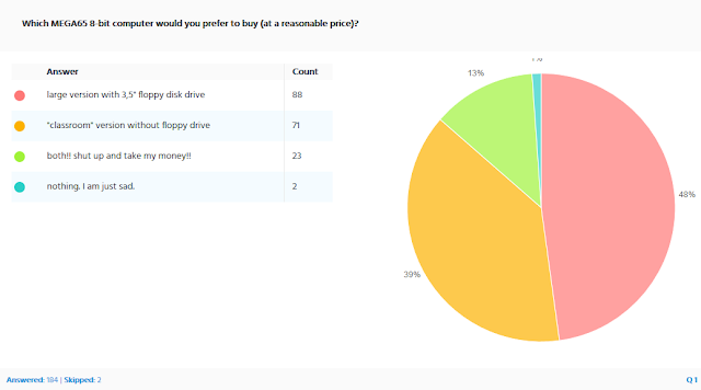
First though, is the question of whether we will include a floppy drive in the MEGA65.  The survey confirmed our existing belief, that more people would like the MEGA65 to have a floppy drive than those against:


We had a total of 184 valid answers from mostly Europe, North America and Australia, with special mentions for Argentina and Iceland.  I was a bit surprised to not see any entries from New Zealand, but that's okay.  Basically we see a general matching of interest to where the Commodore 8-bit computers were well known.  What is most interesting is that on a per-capita basis, it is Denmark and then Australia and Germany that have the highest number of responses.  But enough of me in academic data analysis mode! 


So given that more people want the drive in than out, we had to figure out how and where we could find enough floppy drives for those who want them (we will still likely make the inclusion of the drives optional).

Of course floppy drives are no longer manufacturered, and although as recently as 2016 or 2017 we were able to find brand-new stock in Chinese warehouses, we have had no such luck this time around.  

We even called the German headquarters of ALPS who still make various switches and things, but no longer floppy drives, if they had a few palettes of them hidden away some where.  This was quite a nice call with them, and they were very sympathetic, but unfortunately knew of no stock anywhere.  They did reveal something interesting though: Apparently they are being asked about floppy drives more frequently of late.  Could it be that floppies will make a come back like vinyl records? Probably not.

Anyway, so we had to try to find a large quantity of floppies, but recognised that they would likely have to be used ones, rather than new ones.  But even if they were used, we wanted to find a single supplier with a single model of drive, so that we don't have to worry about eject buttons with different mechanisms or locations to interface to the case etc.

After some searching, we found what we were after: A local supplier here in Germany who has some quantity of different models, including a large number of ALPS 3.5" 1.44MB drives.  This was as good as we could hope for, as the ALPS drives are built like little tanks.  They kindly sent us some very fancy photos of an example drive for us to look at:


 They even took the top off one to show us the internals:

Note that this drive had the front panel removed, which we had requested, so that we could see the eject button mechanism etc, since in the MEGA65 only the slot will be visible.

So, we were satisfied we had a solution, and have thus bravely ordered our first shipment of floppy drives, which is also the first component we have purchased in bulk for the first production run of the MEGA65, which is a little milestone in itself.  After a tense couple of weeks of not receiving a tracking number for the shipment, they suddenly arrived yesterday.  Here are some shots of me starting to unpack several hundred floppy drives:


So now we need to make sure that everything will work together as expected, and have one of these drives connected to the R1 PCB prototypes of the MEGA65 here in Darmstadt:

Fixing Sprite Rendering Problem

After all the fiddling around with video modes a while back, a bug with sprite handling has crept in, where gaps would appear between sprites that were placed side-by-side, e.g., as in the big planet display on Gyrrus:


Or between the halves of the 16-colour sprites in Daniel's Beach Demo test program for the MEGA65:


At first I thought it was pixel edge timing funniness, but it turns out after a little inspection that the left column of pixels in a sprite are only one pixel wide instead of the correct two pixels wide (when at 320x200), as I was able to confirm by setting the first few pixels in the left and right column to check for clues.  So, the question is what is causing this problem?

To figure out the likely cause, I first checked to make sure that the problem happens whether or not sprites are horizontally expanded, and indeed, it does. Also, it is still exactly one physical pixel that is missing, i.e., the gap does not get wider if the sprites are horizontally expanded.

This suggests something about the logic that triggers when on a raster line a sprite should begin being drawn is to blame.  Quite possibly it triggers the logic to advance the pixels one cycle before it actually begins outputting sprite data.

There is some evidence in support of this, in that if the sprites are set to un-expanded H640 mode, i.e., where each sprite pixel is only one physical pixel wide, then the left pixels simply don't appear.


So I started looking at the logic for the sprite pixel advancing, and found that the sprite left edge could be triggered on a cycle when it is not a visible pixel edge.  As a result, an update happens to the sprite X pixel position on this partially wide pixel.  The fix turned out to be quite simple:

@@ -299,11 +300,19 @@ begin  -- behavioural
 --      else
 --        report "x_in = " & integer'image(x_in) & ", != sprite_x = " & integer'image(to_integer(sprite_x));
 --      end if;
+
+      -- Make sure we don't start a sprite edge except on an output pixel edge,
+      -- to stop the left pixel column being trimmed by one clock tick
+      if (x_in_sprite_soon= '1') and (pixel_strobe = '1')  then
+        x_in_sprite_soon <= '0';
+        x_in_sprite <= '1';
+      end if;
+
       if (x_in = to_integer(sprite_x))
         and (x_in /= x_last)
         and (sprite_enable='1')
         and ((y_top='1') or (sprite_drawing = '1')) then
-        x_in_sprite <= '1';
+        x_in_sprite_soon <= '1';         x_expand_toggle <= '0';
         report "SPRITE: drawing row " & integer'image(y_offset)
           & " of sprite " & integer'image(sprite_number)


Basically I have added an extra signal that notes when the sprite X starting position is reached, but then delays it until the next physical pixel edge.  I like it when things are simple to fix.  The result is that the problem is corrected, as the following screen-shots show:


Now if I only I can fix the remaining bitplane problems so quickly.  But that will have to wait for another post.