
First, the front: Nothing too much to see here, except that of course we don't yet have the joystick direction and buttons populated, nor the speaker, volume thumb-wheels or system buttons at the bottom:

Then the rear side, where there is a lot more happening:

Here we can see a couple of ICs are mmissing, which we have noted. The big one with lots of space between the pins is the ADC for the headphone microphone. The little 8-pin job near the middle of the image, I don't specifically recall what it is, just that it isn't important for initial testing.

Here we can see the power supply for the FPGA and two other sub-systems near the middle (small black chip with cluster of little components around them). One of those had a loose resistor, which we had to fix. Also, on the upper left, we can see an 8-pin header. This should be female, and is for the ESP8266 Wi-Fi module.
Immediately above that is the bluetooth chipset, which is quite flexible, and should allow the MEGAphone to use headsets, as well as to act as a set of bluetooth speakers, if you ever had the need. To the right of that the big white thing is a full sized SIM/SmartCard reader. I've got plans for that, that I will write about in another post. Then below that is the wide connector for the LCD panel, and the little white thing somewhat to the left of that is the connector for the touch screen digitiser. We already know that the LCD connector needs too be about 1cm to the right, and that both should be a couple mm lower down on the board. You can also see the pair of LoRa radios, which give tri-band UHF functionality at 434MHz, 868MHz and 915MHz. Those are there because I like resilient telecommunications solutions. It also means it should be possible to play multiplayer games upto several km distance between players :)
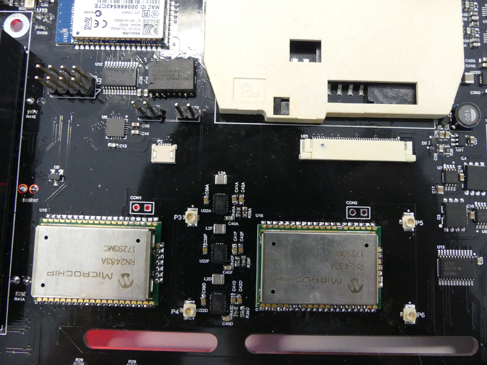

Also, it turns out the SIM card slots we got are too tall to sit beneath the modem slots, so we will need to do something about that. The big green thing to the right is the battery connector.


Now, back to the LCD screen, we spotted another issue: the 5mm LEDs don't leave enough space for the digitiser to sit flat:


Looks like it should work :)
Okay, so that's a quick walk through the hardware. Now to try to get it to power up and do something.
Very interesting project Paul !
ReplyDeleteI am closely following it as i follow the Mega65 !
Looking forward to see a youtube video ;-)
Best regards,
Anton
This project is perverse and I am here for it. Super looking forward to getting my hands on it. I wrote an article years ago about security through obscurity and obsolescence as obfuscation and this is definitely that but taken to a whole new level. Amazing stuff.
ReplyDelete